Quick Start Guide
D103556X012
DVC6200 Digital Valve Controllers
August 2015
16
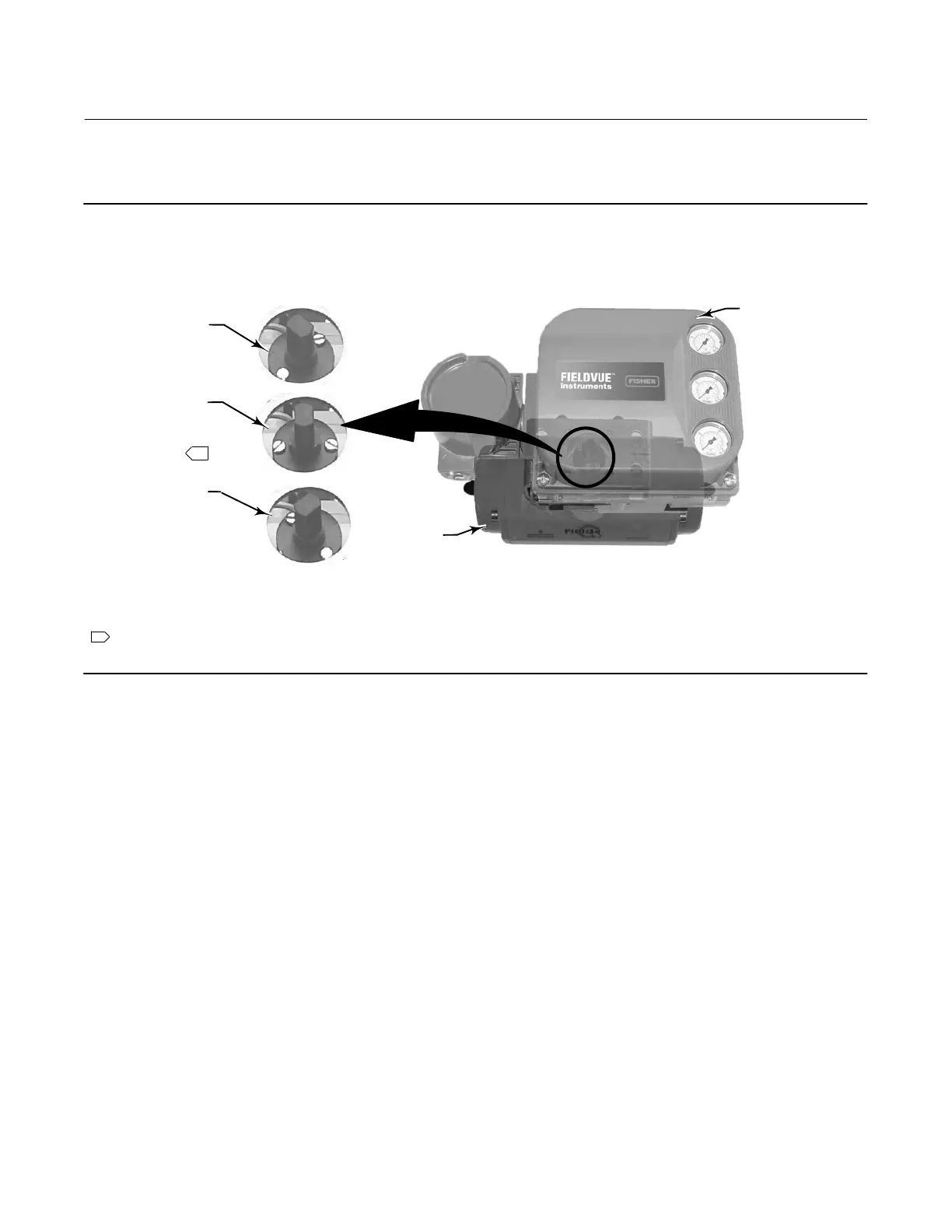
2. Attach the magnet assembly to the actuator shaft. At mid‐travel, the flats on the magnet assembly should be
approximately parallel to the channel on the back of the DVC6200 housing, as shown in figure 13.
W9700
ORIENTATION
AT MID‐TRAVEL
(FLATS PARALLEL
TO DVC6200
CHANNEL)
ORIENTATION
AT THE OTHER
TRAVEL EXTREME
ORIENTATION
AT ONE TRAVEL
EXTREME
Figure 13. Magnet Assembly Orientation on Quarter‐Turn Actuators
ACTUATOR
DVC6200
1 THIS EXAMPLE SHOWS AN ACTUATOR WITH 90_ TRAVEL. ON AN ACTUATOR THAT HAS LESS THAN 90_ TRAVEL THE MAGNET ASSEMBLY MAY NOT BE
PARALLEL AT THE MID-TRAVEL POINT. TO VERIFY THE MAGNET ASSEMBLY POSITION IS IN WORKING RANGE, CONFIRM TRAVEL COUNTS ARE WITHIN THE
EXPECTED RANGE OF 175-3800 USING VALVELINK SOFTWARE OR A FIELD COMMUNICATOR.
1
3. Install the mounting bracket on the actuator.
4. Attach the digital valve controller to the mounting bracket using the 4 mounting bolts, as shown in figure 12.
5. Check for clearance between the magnet assembly and the DVC6200 feedback slot.
6. For remote mount applications, proceed to page 17 for DVC6205 base unit mounting. Otherwise, proceed to
Step 2—Connect the Pneumatic Tubing on page 19.
 Loading...


