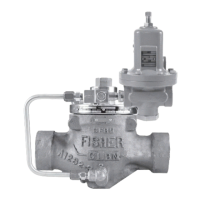
Type LR125
16
Type 112 Restrictor Maintenance
Avoid personal injury or damage to
property from sudden release of pressure
or uncontrolled process uid. Before
starting to disassemble, carefully release
all pressures according to the shutdown
procedure. Use gauges to monitor inlet,
loading and outlet pressures while
releasing these pressures.
Note
Accumulated dirt, mineral deposit,
clogged debris or sediment buildup
inside the restrictor may cause the
unit response to get slower and unit
performance to decrease. If any of these
is suspected, immediately inspect and
clean the restrictor.
Perform the following procedure if O-rings are
leaking or if there is a need to inspect and remove
accumulated dirt, mineral deposit, clogged debris or
sediment buildup inside the restrictor. Key numbers
are referenced in Figure 16.
1. Unscrew the groove valve (key 22) and retainer
(key 23) just enough to loosen them, but do not
completely separate.
2. As shown in Figure 8, push on the retainer (key 23)
to push the groove valve (key 22) out of the body
(key 21), then complete disassembly.
3. Inspect the gaps and small spaces inside
the restrictor. Check and remove any debris,
accumulated dirt, mineral deposit or sediment
buildup that clogs the restrictor.
4. Replace the groove valve O-rings (key 24) if
necessary, being sure to lightly apply lubricant to
the replacement O-rings before installing them in
the groove valve and retainer.
5. Install the groove valve (key 22) into the same
side of the body where the scale appears. Install
the retainer into the opposite side of the body, and
tighten until both are secure.
6. When all maintenance is complete, refer to the
Startup and Adjustment section to put the regulator
back into operation.
Parts Ordering
When corresponding with your local Sales Oce about
this equipment, reference the equipment serial number
or FS number found on a nameplate attached to the
bonnet. When ordering replacement parts, reference
the key number of each needed part as found in
the following parts list. Separate kit containing all
recommended spare parts is available.
Parts List
Type LR125 Main Valve (Figures 10 to 14)
Key Description Part Number
Parts Kits
Diaphragm Cartridge and O-rings (Included are keys 5,
6, 8, 9, 10, 11, 13, 14, 16, 18, 28, 70, 129 and 130)
1 in. / DN 25
17E68 Nitrile (NBR) RLR1258N182
17E97 Nitrile (NBR) RLR1258N172
17E88 Fluorocarbon (FKM) RLR1258F182
2 in. / DN 50
17E68 Nitrile (NBR) RLR1258N282
17E97 Nitrile (NBR) RLR1258N272
17E88 Fluorocarbon (FKM) RLR1258F282
3 in. / DN 80
17E68 Nitrile (NBR) RLR1258N382
17E97 Nitrile (NBR) RLR1258N372
17E88 Fluorocarbon (FKM) RLR1258F382
4 in. / DN 100
17E68 Nitrile (NBR) RLR1258N482
17E97 Nitrile (NBR) RLR1258N472
17E88 Fluorocarbon (FKM) RLR1258F482
1 Valve Body See Table 11
2 Bonnet Assembly
1 in. / DN 25 body
Steel 39B2403X022
Stainless steel ERAA00892A1
2 in. / DN 50 body
Steel 38B2122X022
Stainless steel ERAA00893A1
3 in. / DN 80 body
Steel 38B5963X022
Stainless steel ERAA00894A1
4 in. / DN 100 body
Steel 38B2133X022
Stainless steel ERAA00895A1
3 Cap Screw (For Steel Bonnet)
1 in. / DN 25 body (4 required) 1R281124052
2 in. / DN 50 body (8 required) 1A453324052
3 in. / DN 80 body (8 required) 1A454124052
4 in. / DN 100 body (8 required) 1A440224052
4 Hex Nut (For bodies with travel indicator, 2 required)
1 and 2 in. / DN 25 and 50 bodies,
Zinc-plated Carbon steel 1H322228982
3 and 4 in. / DN 80 and 100 bodies,
Stainless steel 1L286338992
5 Top Plug, Stainless steel
1 in. / DN 25 body 29B2404X012
2 in. / DN 50 body 28B2130X012
3 in. / DN 80 body 28B8511X012
4 in. / DN 100 body 28B5964X012
*Recommended spare part.
- continued -
!
WARNING

 Loading...


