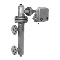
Type LR125
3
!
WARNING
Pilot Type Description
Type MR95H — Pressure reducing pilot for 15 to
150 psig / 1.0 to 10.3 bar outlet pressures. Designed
to handle inlet pressures up to 300 psig / 20.7 bar.
Type MR95HP — Pressure reducing pilot for 15 to
400 psig / 1.0 to 27.6 bar outlet pressures. Designed
to handle inlet pressures up to 600 psig / 41.4 bar.
Principle of Operation
As long as the outlet (control) pressure is above
the outlet pressure setting, the pilot valve plug or
disk remains closed (Figure 2). Force from the main
spring, in addition to inlet pressure bleeding through
the restrictor, provide downward loading pressure to
keep the main valve diaphragm and plug assembly
tightly shuto.
When the outlet pressure decreases below the pilot
outlet pressure setting, the pilot plug or disk assembly
opens. Loading pressure bleeds downstream through
the pilot faster than it can be replaced through the
supply line. This reduces loading pressure on top of
the main valve diaphragm and plug assembly and
lets the unbalanced force between inlet and loading
pressure overcome the main spring force to open the
Type LR125 diaphragm and plug assembly.
As the outlet pressure rises toward the outlet pressure
setting, it compresses the pilot diaphragm against
the pilot control spring and lets the pilot valve plug
or disk close. Loading pressure begins building on
the Type LR125 diaphragm and plug assembly. The
loading pressure, along with force from the main
spring, pushes the diaphragm and plug assembly onto
the tapered-edge seat, producing tight shuto.
Type LR125 Installation
Personal injury, equipment damage or
leakage due to escaping process uid
or bursting of pressure-containing
parts may result if this regulator is
overpressured or is installed where
service conditions could exceed
the limits given in Specications
section or where conditions exceed
any ratings of the adjacent piping or
piping connections.
To avoid such injury or damage, provide
pressure-relieving or pressure-limiting
devices (as required by the appropriate
code, regulation or standard) to prevent
service conditions from exceeding limits.
Additionally, physical damage to the
regulator could break the pilot o the
main valve, causing personal injury
and property damage due to escaping
process uid. To avoid such injury
and damage, install the regulator in a
safe location.
Table 1. Type LR125 Main Valve Body Sizes, End Connection Styles, Structural Design Ratings
and Maximum Operating Inlet Pressures
(1)
MAIN VALVE BODY SIZES
MAIN VALVE BODY
MATERIAL
END CONNECTION STYLES
(2)
STRUCTURAL DESIGN
RATING
(3)
MAXIMUM OPERATING
INLET PRESSURE
(3)
In. DN psig bar psig bar
1, 2, 3 and 4 25, 50, 80 and 100
WCC Steel
NPT or SWE
(1 and 2 in. only)
1500 103 600 41.4
CL150 RF 290 20.0 290 20.0
CL300 RF 750 51.7
600 41.4CL600 RF 1500 103
PN 16/25/40 RF
(4)
580 40.0
CF8M Stainless Steel
NPT
(1 and 2 in. only)
1440 99.2 550 37.9
CL150 RF 275 19.0 275 19.0
CL300 RF 720 49.6
550 37.9CL600 RF 1440 99.2
PN 16/25/40 RF
(4)
580 40.0
1. The pressure/temperature limits in this Instruction Manual and any applicable standard or code limitation should not be exceeded.
2. Ratings and end connections for other than ASME standard can usually be provided. Contact your local Sales Oce for assistance.
3. Maximum cold working pressure (CWP) per ASME B16.34 or product bulletin limit, whichever is lowest. Temperature may decrease these maximum pressures.
4. Not available for 4 in. / DN 100 body size.

 Loading...