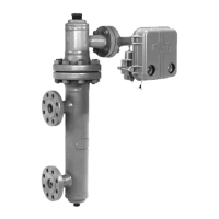
Type LR125
9
!
WARNING
!
WARNING
Type 112 Restrictor Adjustment (Figure 5)
The Type 112 restrictor controls the regulator’s
accuracy and speed of response. A restrictor setting
of 4 is recommended to optimize accuracy, speed
of response and stability. However, the restrictor
can be used to ne tune the regulator for maximum
performance by decreasing the restrictor setting for
tighter control (increased opening speed, decreased
closing speed); or increasing the restrictor setting
for maximum stability (decreased opening speed,
increased closing speed). A lower setting also provides
a narrower proportional band for better accuracy. The
“8” position has the largest ow, is most stable and
easiest for startup, however, using the “8” position
is not necessary. The “0” setting has the smallest
(minimum) ow passage; at no point of rotation will the
Type 112 restrictor be completely shut o. After initial
adjustment, the restrictor does not need to be adjusted
for maintenance or startup.
Note
Mineral, dirt and sediments may gradually
deposit and build up inside the spaces
of the restrictor. This may cause the
unit response to get slower and unit
performance to decrease. If clogging of the
restrictor is suspected, immediately check
and clean the restrictor. Regular inspection
of the restrictor is recommended to
ensure optimum performance. Refer to the
Type 112 Restrictor Maintenance section.
Likewise, debris in the process uid
may clog the restrictor. Install strainer
upstream of the regulator to prevent
debris from clogging the restrictor.
Regular inspection, maintenance and
cleaning of the strainer is recommended
to ensure optimum performance.
Recommended Type 112 Restrictor
Setting Guide (Figure 5)
This guide can be used to adjust performance
according to application conditions. The recommended
initial setting is 4.
Shutdown
If pilot supply pressure is shut down
rst, the downstream system may be
subjected to full inlet pressure.
1. If the pilot setting must be disturbed, be sure to
keep some tension on the spring. This will prevent
trapping inlet pressure during blow down.
2. Close the valves shown in Figure 3, in the
following order:
a. Inlet block valve
b. Outlet block valve
c. Control line valve(s), if used
3. Open the vent valves to depressurize the system.
Maintenance
Regulator parts are subject to normal wear and
must be inspected periodically and replaced as
necessary. Due to the care Emerson takes in meeting
all manufacturing requirements (heat treating,
dimensional tolerances, etc.), use only replacement
parts manufactured or furnished by Emerson. Also,
when lubrication is required, use a good quality
lubricant and lightly coat the recommended part.
The frequency of inspection and parts replacement
depends upon the severity of service conditions,
applicable codes and government regulations and
company inspection procedures. Table 8 lists possible
regulator issues and solutions for them.
Type LR125 Main Valve Trim Parts
Instructions are given for complete disassembly and
assembly. The main valve may remain in the pipeline
during maintenance procedures. Key numbers are
referenced in Figures 10 through 14.
Avoid personal injury or damage
to property from sudden release of
pressure or uncontrolled process uid.
Before starting to disassemble, carefully
release all pressures according to the
Shutdown procedure. Use gauges to
monitor inlet and outlet pressures while
releasing these pressures.
Disassembly
Disassembly of Type LR125:
1. Shutdown, isolate and depressurize the main valve
and pilot according to the shutdown procedure.
2. Remove the cap screws (key 3). Lift up and
remove the bonnet (key 2) from the body (key 1).

 Loading...