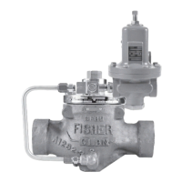
Type LR125
5
B2605_A
!
WARNING
CAUTION
Liquid pressure control systems should
be designed using engineering practices
to eliminate quick control starting or
stopping of the ow stream, which can
produce water hammer.
The robust design of the Type LR125 allows this
regulator to be installed indoors or outdoors. This
regulator is designed to withstand the elements. The
powder paint coating protects against minor impacts,
abrasions and corrosion. When installed outdoors,
the Type LR125 does not require protective housing.
However, the Type MR95H/MR95HP pilot should be
oriented so that the pilot spring case vent is pointed
down. Otherwise, make sure the vent is protected
so that rain, moisture, insects or any debris will not
accumulate inside or block the vent assembly.
When installed indoors, no remote venting is required
except on the pilot spring case. Refer to Step 5 of the
following procedure for the correct venting practices.
1. Only personnel qualied through training and
experience should install, operate and maintain a
regulator. Before installation, make sure that there
is no damage to or debris in the regulator. Also,
make sure that all tubing and piping are clean
and unobstructed.
Note
The Type LR125 internal inlet strainer
is intended to prevent occasional
large particles from entering the main
valve. If the owing media contains
continuous particles, upstream ltration
is recommended before the main
valve and in the pilot supply piping.
See the Specications section for the
corresponding mesh size of the internal
inlet strainer.
2. A Type LR125 regulator may be installed in any
orientation, as long as ow through the regulator
matches the direction of the arrow on the main
valve body and the pilot vent is pointed down.
However, for easier maintenance, install the
regulator with the bonnet up.
Provide adequate support to the bonnet
when disassembling Type LR125
pressure reducing regulator installed in
a vertical installation or other application
where the bonnet is not oriented upward.
Without adequate support, the bonnet
may fall and cause physical injury when
the cap screws are loosened.
TYPE MR95H/MR95HP PILOT INSTALLATION WITH PILOT EXHAUST INTO CONTROL LINE
Figure 3. Typical Type LR125 Installation Schematic
Table 2. Pilot Maximum Operating Pressures
(2)
PILOT BODY SIZE BODY AND SPRING CASE MATERIAL MAXIMUM INLET PRESSURE MAXIMUM OUTLET PRESSURE
Type MR95H 1/2 NPT
Steel
Stainless steel
300 psig / 20.7 bar
300 psig / 20.7 bar
300 psig / 20.7 bar
300 psig / 20.7 bar
Type MR95HP 1/2 NPT
Steel
Stainless steel
600 psig / 41.4 bar
600 psig / 41.4 bar
600 psig / 41.4 bar
550 psig / 37.9 bar
1. The pressure/temperature limits in this Installation Manual, and any applicable standard or code limitation should not be exceeded.
2. Temperature and/or the body end connection may decrease these maximum pressures.
BLOCK VALVE
INLET
SUPPLY PRESSURE LINE
RESTRICTOR
CONTROL LINE
TYPE MR95H/MR95HP PILOT
ALTERNATE CONTROL LINE
HAND VALVE
OUTLET
BLOCK VALVE

 Loading...


