FXMP25 User Guide 23
Issue Number: 3 www.controltechniques.com
Safety information
Product
information
Mechanical
installation
Electrical
installation
Getting started Parameters Setting-up Technical data Diagnostics UL listing information
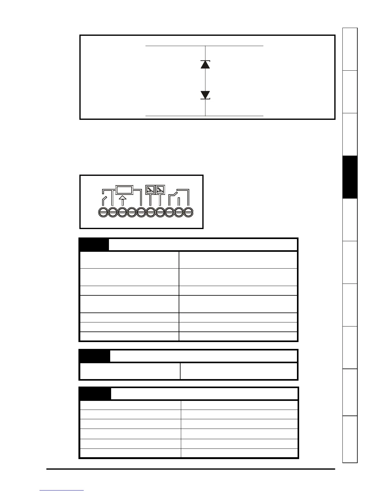
Figure 4-4 Surge suppression for analog and bipolar inputs and outputs
Surge suppression devices are available as rail-mounting modules, e.g. from Phoenix Contact:
Unipolar TT-UKK5-D/24 DC
Bipolar TT-UKK5-D/24 AC
4.7 Control terminal specification
Figure 4-5 Control terminals
Signal from plant Signal to drive
0 V 0 V
2 x 15 V zener diode
e.g. 2xBZW50-15
1 (Ion) Digital input
Dual Function
Field economy select or enable
controller (See Pr 81)
Type
Single ended, negative logic (0 V
common for normal operation)
Voltage range 0 V to 24 V
Absolute maximum applied
voltage range
-18 V to 30 V
Load 2.4 mA at 0 V (sink)
Input threshold High: 11 V, Low: 9 V
Update rate 4 ms
2 (0V) 0V common
Function
Common connection for all external
devices
3 (Iref) Analog input
Function Current demand input
Full scale voltage range 0 to 10 V
Absolute maximum voltage range -18 V to 30 V
Input resistance
44 kΩ
Resolution 10 bits
Sample period 4 ms
Iref
+10V
If
Va
Fail
11 1
2
3
45
6
7
8
910
0V
Ion