FXMP25 User Guide 25
Issue Number: 3 www.controltechniques.com
Safety information
Product
information
Mechanical
installation
Electrical
installation
Getting started Parameters Setting-up Technical data Diagnostics UL listing information
4.8 Serial communications
4.8.1 Introduction
The FXMP25 has a standard 2-wire EIA485 interface (serial communications interface)
which enables all drive set-up, operation and monitoring to be carried out with a PC or
controller if required. Therefore it is possible to control the drive entirely by serial
communications without the need for a keypad or other control cabling.
The drive supports Modbus RTU configured as the default protocol, which is used with
the PC-tools commissioning/start-up software as provided on the CD ROM with the
product.
The serial communications port of the drive is a RJ45 socket, which is isolated from the
power stage.
The communications port applies a 2 unit load to the communications network.
4.8.2 Serial communications connections
The FXMP25 has a serial communications port (serial port) as standard supporting two
wire EIA(RS)-485 communications. See Table 4-8 for the connection details for the
RJ45 connector.
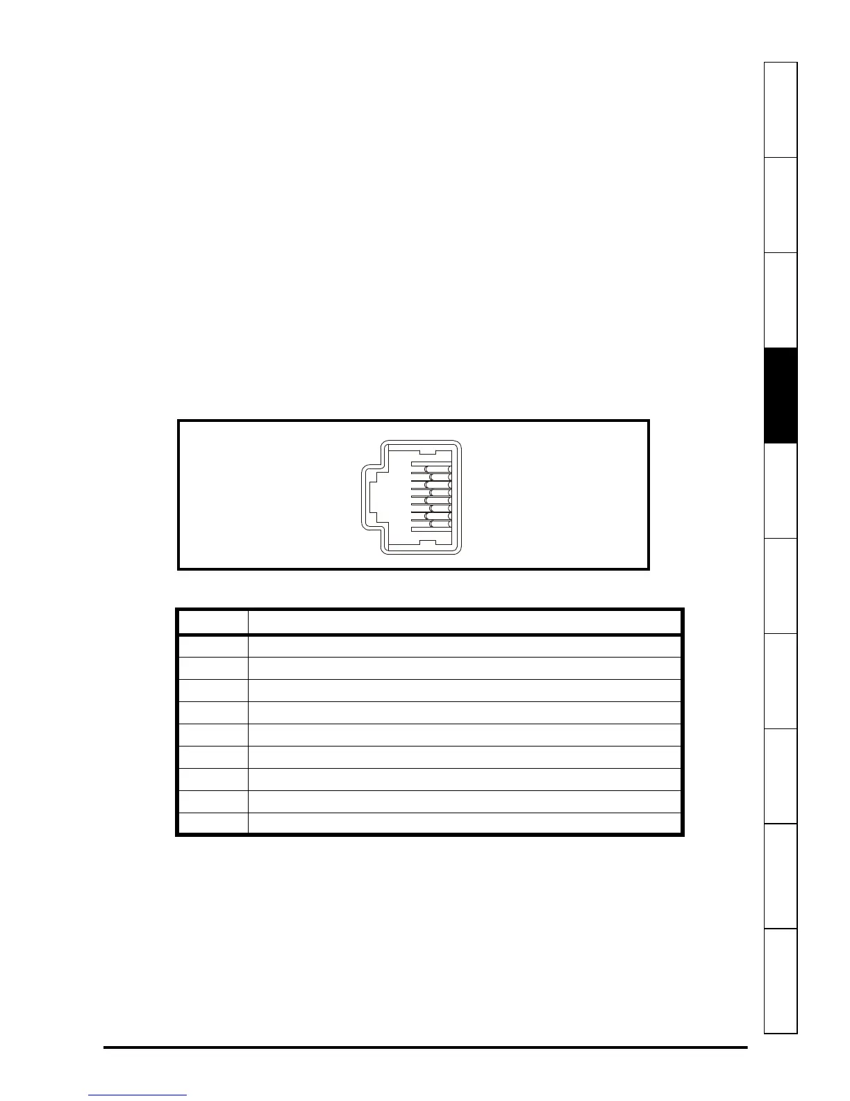
Figure 4-6 Serial communications port
Table 4-8 RJ45 connections
The communications port applies a two-unit load to the communications network.
Connectors 2, 3, 7 and shield must always be made to the serial communications port.
Shielded cable must be used at all times.
USB/EIA232 to EIA485 Communications
An external USB/EIA232 hardware interface such as a PC cannot be used directly with
the 2-wire EIA485 interface of the drive. Therefore a suitable converter is required.
Pin Function
1
120 Ω Termination resistor
2
RX TX
3
0 V isolated
4
+24 V (100 mA)
5
0V isolated
6
TX enable
7
RX\ TX\
8
RX\ TX\ (if termination resistors are required, jumper (link) to pin 1)
Shell
0 V isolated