FXMP25 User Guide 51
Issue Number: 3 www.controltechniques.com
Safety information
Product
information
Mechanical
installation
Electrical
installation
Getting started Parameters
Setting-up
Technical data Diagnostics UL listing information
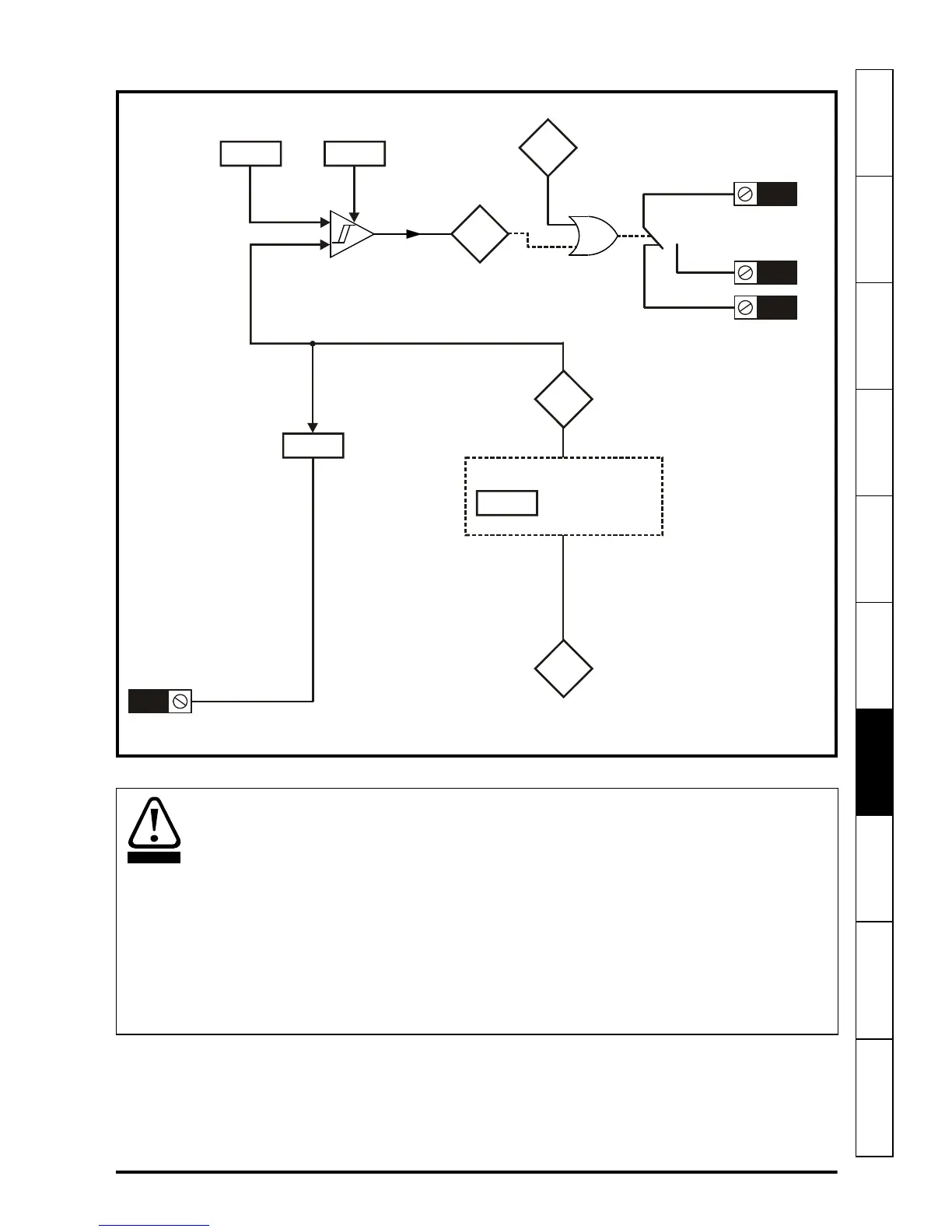
Figure 7-3 Mentor II mode
Refer to Mentor II User Guide Issue 14 page 95 for Mentor II block diagram.
54
Flux
feedback
11
Flux calculator
Mentor II field
feedback setting
07
Field flux
output scaling
A1/A2
If
Field
flux
output
25 26
27
Flux
level
exceeded
A1/A2
A1/A2
A1/A2
Drive healthy
hysteresis level
Drive healthy
flux level
8
9
10
OR
01
Drive
healthy / OK
Thermal overload in Mentor II mode works by forcing current feedback to zero causing
the relay to operate. When Mentor II is enabled, this causes the drive to trip FdL (field
loss). When in the disabled state, FdL trip is not active on Mentor II, and therefore
following loss of feedback Mentor II will advance the firing angle to the end stop which
will cause the output of the FXMP to reach maximum voltage set by the front end stop
Pr 6.21.
When using FXMP 25 with Mentor II, Pr 6.21 must be set in order to avoid field over
voltage conditions during fault conditions. (Refer to Pr 6.21 on page 64 in the Mentor II
User Guide for an example calculation). FXMP relay and Mentor II logic functions
should be used to set Pr 6.13 to 0 to disable firing pulses during fault conditions in the
disabled state.

 Loading...