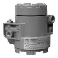
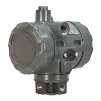
i2P-100 Transducer
Instruction Manual
Form 5777
September 2004
13
6. When replacing the input diaphragm (key 38),
make sure all passages and screw holes are
aligned. Place the input diaphragm on the body
block (key 40). Hold assembled parts in place.
7. Install the bias spring (key 34) into the transducer
housing assembly (key 1). Make sure the tabs on
the body block and relay body align with the tab on
the transducer housing assembly. Place the
assembled parts onto the transducer housing
assembly. Thread the two mounting screws (key 36)
into the transducer housing assembly. Install the
remaining two mounting screws. Tighten all
mounting screws to 2 NSm (20 lbfSin).
8. Perform the procedure in the Calibration section
of this manual.
Parts Ordering
A serial number is assigned to each transducer and
stamped on the nameplate. Always refer to this
serial number when corresponding with your Fisher
sales office regarding spare parts or technical
information. When ordering replacement part, also
specify the complete 11-character part number from
the Parts list.
Note
Use only genuine Fisher replacement
parts. Components that are not
supplied by Fisher should not, under
any circumstances, be used in any
Fisher instrument. Use of components
not supplied by Fisher will void your
warranty, might adversely affect the
performance of the instrument, and
might jeopardize worker and
workplace safety.
Note
Fisher does not assume responsibility
for the selection, use and maintenance
of any product. Responsibility for the
selection, use and maintenance of any
Fisher product remains solely with the
purchaser and end-user.
Parts List (see figure 13)
Housing
Key Description Part Number
1 Housing, Aluminum
2 Cover (2 req’d) 48B6515X022
3 Configuration Label GE03345X012
4* O-Ring (2 req’d) 1K1810X0102
6 Feed Thru (2 req’d) GE03087X012
7 Wire Retainer (2 req’d) 16A2821X012
8 Set Screw (2 req’d) 1B4556X0012
9* O-Ring GC070193X13
10 Restrictor, Primary 10C2233X012
11* Filter 10C2246X012
12* O-Ring 14A1968X032
13 Filter Cap GB0122X0012
14 Machine Screw (2 req’d) 19B0821X012
15 Flame Arrestor GE06959X012
16 Flame Arrestor GE02963X012
17 Sealant, Silicone (not furnished with transducer)
18 Loctite 271 Sealant or equivalent (not furnished
with transducer)
19 Adhesive
55 O-Ring 1C8538X0162
69 Nameplate, CSA approvals, aluminum - - -
70 Screw (2 req’d) 1P426928982
71 Vent Assembly GE06162X012
76 Pipe Plug 1H5137X0012
*Recommended spare parts
 Loading...