Do you have a question about the Emerson i2P-100 and is the answer not in the manual?
Details the installation, operation, maintenance, and parts ordering information for the i2P-100 transducer.
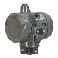
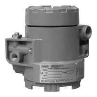
Describes the transducer's function, input/output signals, and typical application.
Information on available courses for the Type i2P-100 Transducer and other products.
Details on installing the i2P-100 transducer with air or natural gas, including venting requirements.
Covers factory mounting, separate mounting on valve assemblies, pipestands, or flat surfaces.
Details the 0.25 inch NPT female connections for pressure and vent, and tubing size.
Specifies requirements for clean, dry air or noncorrosive gas supply, recommending a filter regulator.
Describes special connectors and hardware for diagnostic testing of valve/actuator/positioner packages.
Discusses venting the supply medium to the atmosphere, remote venting requirements, and vent line piping.
Covers installation of field wiring using the 0.5 inch NPT conduit connection and terminal connections.
Explains the normal mode of operation, requiring pneumatic output to be piped to the final control element.
Details the process of calibrating the transducer, including equipment and procedure.
Lists the necessary equipment for calibration, such as a current or voltage source.
Provides step-by-step instructions for calibrating the transducer, including adjustments.
Explains how the converter module operates using a force-balanced beam system and nozzle/flapper arrangement.
Discusses periodic maintenance, troubleshooting, inspection, and replacement of component parts for the transducer.
Provides procedures for electrical and pneumatic troubleshooting of the transducer.
Details the removal and replacement procedures for the converter module.
Details the removal and replacement procedures for the electronics module.
Provides step-by-step instructions for the removal, inspection, and reassembly of the relay.
Explains how to order replacement parts, referring to serial numbers and part numbers.
Lists the components of the transducer with their corresponding part numbers.
Lists various mounting brackets, washers, and screws for different actuator sizes.
| Type | I/P Transducer |
|---|---|
| Power Supply | 20-30 VDC |
| Accuracy | ±0.5% of span (typical) |
| Operating Temperature | -40 to 85°C (-40 to 185°F) |
| Approvals | CE |