28 Chapter 3 Parallel UPS Installation And Commissioning
Liebert
®
ITA 16kVA And 20kVA UPS User Manual
1 + 1 parallel
POD (1 pcs)
UPS (2 pcs)
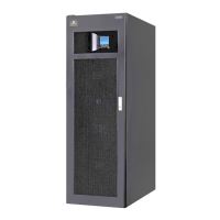
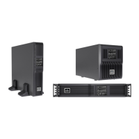
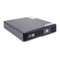
Figure 3-1 1 + 1 parallel system installation (without battery module)
3.4 Connecting Power Cables
Each single UPS of the parallel system needs to configure the MCB and cables respectively, refer to 2.5 Connecting
Power Cables for the specification. The recommended configurations of the total power cables are listed in Table 3-1
for the parallel system.
Table 3-1 Input & output cable CSA for the parallel system (unit: mm
2
, ambient temperature: 25
℃
)
3-in 3-out 3-in 1-out
Parallel UPS
number
Single input
cable for
parallel
system
Single output
cable for
parallel
system
Total neutral
line for
parallel
system
Grounding
cable for
parallel
system
Total output
cable for
parallel
system
Total neutral
line for
parallel
system
Grounding
cable for
parallel
system
2 units 25 25 35 16 70 120 35
3 units 35 35 50 16 150 240 75
4 units 50 50 70 25 240 370 120
3.4.1 Connecting I/O Cables
The power cables of the UPS are connected to the I/O terminal block of the rear panel of the UPS, the layout of the
I/O terminal block is shown in Figure 2-13.
Power distribution mode
There are two modes for UPS parallel power distribution: using the 1 + 1 parallel POD (optional) provided by
Emerson, self-distribution.
The I/O cable connections are divided into four types: 3-in 3-out, common source configuration (factory default), 3-in
3-out, split-bypass configuration, 3-in 1-out, common source configuration, 3-in 1-out, split-bypass configuration. The
I/O cable connection procedures of the four self- distribution modes are as follows.
1. Using parallel POD power distribution
It is recommended to use 1 + 1 parallel POD power distribution mode if you need 1 + 1 parallel system, for the
installation and commissioning, refer to Liebert
®
ITA 16kVA And 20kVA UPS Power Output Distribution Unit User
Manual.
2. Self-distribution for the parallel system
When the UPS number of the parallel system is more than two, use self-distribution mode.
The block diagram of three UPSs parallel system is shown in Figure 3-2. Refer to Power distribution mode in
2.5.1 Connecting I/O cables for the cable connection of each UPS. Refer to 2.5 Connecting Power Cables for the
input and output MCB, the battery MCB and the cables when using the self-distribution mode.
 Loading...
