Single Module UPS Installation
13
Figure 4 Jumper connection for BCB interface
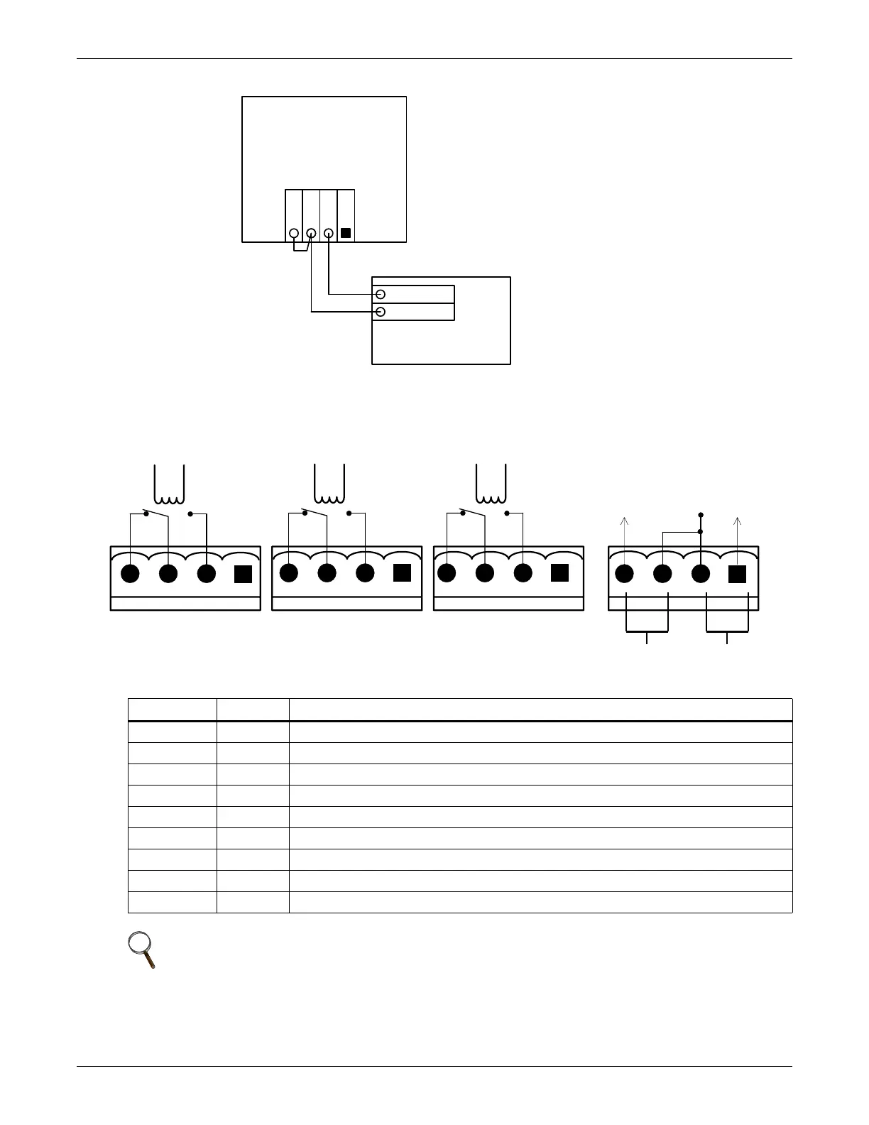
1.8.4 Output Dry Contacts
There are three output dry contact relays at the X1 slot (see Figure 5 and Table 6). The relay con-
tacts are suitable for extra-low voltage applications up to 1A.
Figure 5 Output dry contacts and EPO wiring
Table 6 Output dry contact relays
Position
Name
Description
J13.2 BFP_O Bypass feedback protection relay; normally open; closed when bypass SCR is shorted
J13.3 BFP_S Bypass feedback protection relay center
J13.4 BFP_C Bypass feedback protection relay; normally closed; open when bypass SCR is shorted
J21.2 INV_O Inverter mode relay; normally open; closed when UPS is in inverter mode
J21.3 INV_S Inverter mode relay center
J21.4 INV_C Inverter mode relay; normally closed. Opened when UPS is in inverter mode
J25.2 ACF_O Main input fault relay; normally open. Closed when main input is in fault
J25.3 ACF_S Main input fault relay center
J25.4 ACF_C Main input fault relay; normally closed. Open when main input is in fault
NOTE
All auxiliary cables of terminal must be double-insulated. Wire should be 0.5-1.5mm
2
(16-20AWG) stranded for maximum runs between 25 and 50 meters (82-164ft.) respectively.
UPS Monitoring Board
J10
OL
DRV
GND
FB
Battery Circuit Breaker
OL
Aux – N.O.
Aux – N.O.
EPO - NCEPO - NO
X2X1
BFP_C
J21 J25 J28
BFP_S
BFP_O
INV_O
INV_S
INV_C
ACF_C
ACF_S
ACF_O
J13
+12V