Safe Use Instructions – MVS205
Form A6154
Page 2
Specifications
DIFFERENTIAL PRESSURE INPUT
Range: 0 to 6.22 kPa, 0 to 62.2 kPa, or 0 to
248.8 kPa.
Reference Accuracy:
±0.075% of Upper Range Limit (for MVS205P)
Includes linearity, hysteresis, and repeatability
effects for URL up to 10:1 turndown.
±0.10% of Upper Range Limit (for MVS205E).
STATIC PRESSURE INPUT
Range: Either Absolute or Gauge:
0 to 5516 kPa or 0 to 25,000 kPa
Reference Accuracy:
±0.075% of Upper Range Limit (for MVS205P)
Includes linearity, hysteresis, and repeatability
effects for URL up to 6:1 turndown.
±0.10% of Upper Range Limit (for MVS205E).
PROCESS TEMPERATURE INPUT
Type: For 3 or 4-wire platinum 100-ohm RTD
(conforming to IEC 751 Class B), with α =
0.00385.
Range: –40 to 400°C.
Reference Accuracy: ±0.28°C, exclusive of
RTD sensor error. Specification includes
linearity, hysteresis, and repeatability effects.
Excitation Current: 1.24 mA.
POWER
Input at 0 to 75°C: 8 to 30 V dc, 245 mW
average. Input at -40 to 0°C: 8.5 to 30 V dc,
245 mW average. Supplied by ROC/FloBoss.
WEIGHT
Including head, 3.0 kg.
ENVIRONMENTAL
Operating Temperature: –40 to 75°C.
Storage Temperature: –50 to 85°C.
Operating Humidity: 0 to 99%, non-
condensing.
Radiated/Conducted Immunity: Meets
requirements of IEC 61326 Electrical
Equipment for use in Industrial Locations.
Radiated Emissions: Meets EN 55022 Class
B and ICES-003:1997 Digital Apparatus.
CONSTRUCTION
Sensor Body and Coplanar Flange: 316
SST.
Wetted Parts: 316 SST is standard; Wetted
O-rings are glass-filled TFE. Hastelloy C
(NACE compliant) is available.
Electronics Head: Urethane-painted die-cast
aluminum alloy, rated IP66.
APPROVALS
Evaluated per the following European
standards:
EN 60079–0 (2006).
EN 60079–1 (2007).
EN 61241–0 (2006)
EN 61241–1 (2004)
EN 60529 (2001).
Certified by KEMA as Model MVS205R.
Product Markings for Hazardous Locations:
Ex d IIB T5 (T
amb
=75°C).
Ex tD A21 IP66 T85°C.
II 2 GD. 0081.
ATEX Cert. KEMA 04ATEX2182 X
IEC Cert. IECEx KEM 07.0055X
The following tools are required for installation,
maintenance and troubleshooting:
IBM-compatible personal computer.
ROCLINK™ 800 Configuration Software.
Phillips-head screwdriver.
Flat-head screwdriver.
Hex socket wrench (3/8-inch).
Hex socket wrench (7/16-inch).
Allen hex wrench (3 mm).
1. Remove the MVS205 Sensor from the
shipping box.
2. Find a suitable location for the MVS205
Sensor. Check all clearances when choosing an
installation site. Provide adequate clearance for
wiring and service.
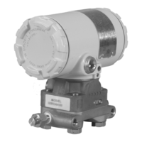
3. The Coplanar™ flange on the bottom of the
MVS205 Sensor body allows mounting on a
pipestand, wall, panel, or to the flange taps of
an integral orifice assembly or manifold valve.
The MVS205 can be mounted to a panel or pipe
(see Figure 3, Figure 4, and Figure 5) with the
optional bracket kit, which includes an L-shaped
bracket and a pipe clamp. The bracket kit
attaches to the coplanar flange at the pressure
connector.



 To Next Page