Do you have a question about the Emerson Net Safety Millennium II and is the answer not in the manual?
Details the seller's warranty terms and conditions for the product, including exclusions and limitations.
Defines the seller's liability limits and exclusive remedies for product-related claims, excluding consequential damages.
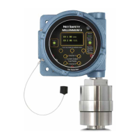
Guidelines for securely mounting the transmitter and sensor, including orientation options.
Covers general requirements and best practices for wiring the transmitter and sensors.
Highlights essential safety precautions and general guidelines for electrical wiring.
Emphasizes the critical role of wiring in safety systems and RFI/EMI mitigation.
Details jumper settings for configuring analog output as isolated or non-isolated.
Provides terminal designations and wiring connections for sensors and transmitter power/outputs.
Guidelines for mounting sensors remotely, including junction box and cable selection.
Lists available functional settings and options accessible through the transmitter's menu system.
Procedure for performing calibration on the connected sensor.
Allows users to enable or disable individual sensor channels (CH1, CH2).
Enables setting and viewing low and high alarm levels for each channel.
Configures alarm relay coils as energized/de-energized and latching/non-latching.
Assigns alarm relays (RL1-3) to specific channels (CH1-2) and alarm points.
Configuration of Modbus parameters like address, baud rate, and parity.
Performs a reset after calibration failure or to clear latched alarms.
Initiates a test of the transmitter's relays to ensure proper functioning.
Step-by-step guide for performing a complete calibration of the sensor.
Describes the 4-20 mA output for transmitting status, fault codes, and gas concentration.
Explains HART protocol for advanced communication with the single-channel transmitter.
Details the Form-C SPDT relays for fault and alarm signaling.
Covers the optional RS-485 Modbus RTU protocol for data communication.
Lists Modbus registers, their meaning, and readability/writability.
Describes the system's self-testing and fault detection mechanisms.
Details critical indicators of device malfunction that override alarm conditions.
Recommends 90-day bump tests to ensure continued system functionality and accuracy.
| Brand | Emerson |
|---|---|
| Model | Net Safety Millennium II |
| Category | Transmitter |
| Language | English |