8 AGL_Sol_PEC_01_E_Rev01
Figure 2: Temperature measurement accuracy (total error) NTC 10 KΩ
2.3.1.4 Digital inputs
Opto-insulated / free voltage contacts
1 DI 24-240 VAC/DC, opto-isolated
2 DI 24 VAC dry contact, potential free
Digital input status variation detection time
Table 5
2.3.1.5 Digital outputs
Type of output
(configurable via software parameter)
Relays with normally open contact
(except LD1 that is normally closed)
230 VAC (5 A resistive, 2 A inductive cos φ 0.5)
Verify the capacity of the output used.
There is double insulation between the digital outputs
and the low voltage of the rest of the circuit.
Table 6
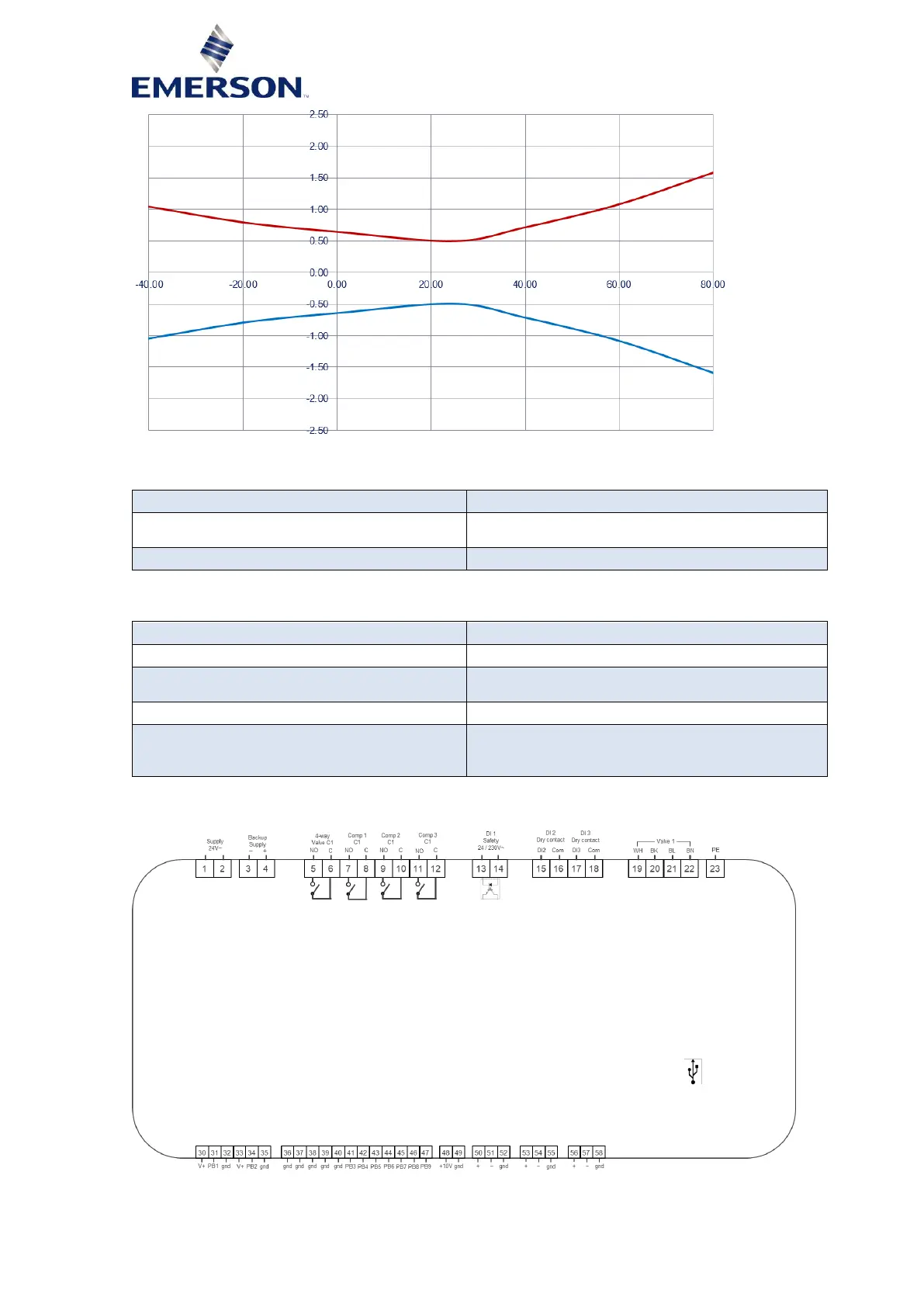
2.3.1.6 Wiring diagram PeC C100
Figure 3