10 AGL_Sol_PEC_01_E_Rev01
2.3.2 PeC C200 controller
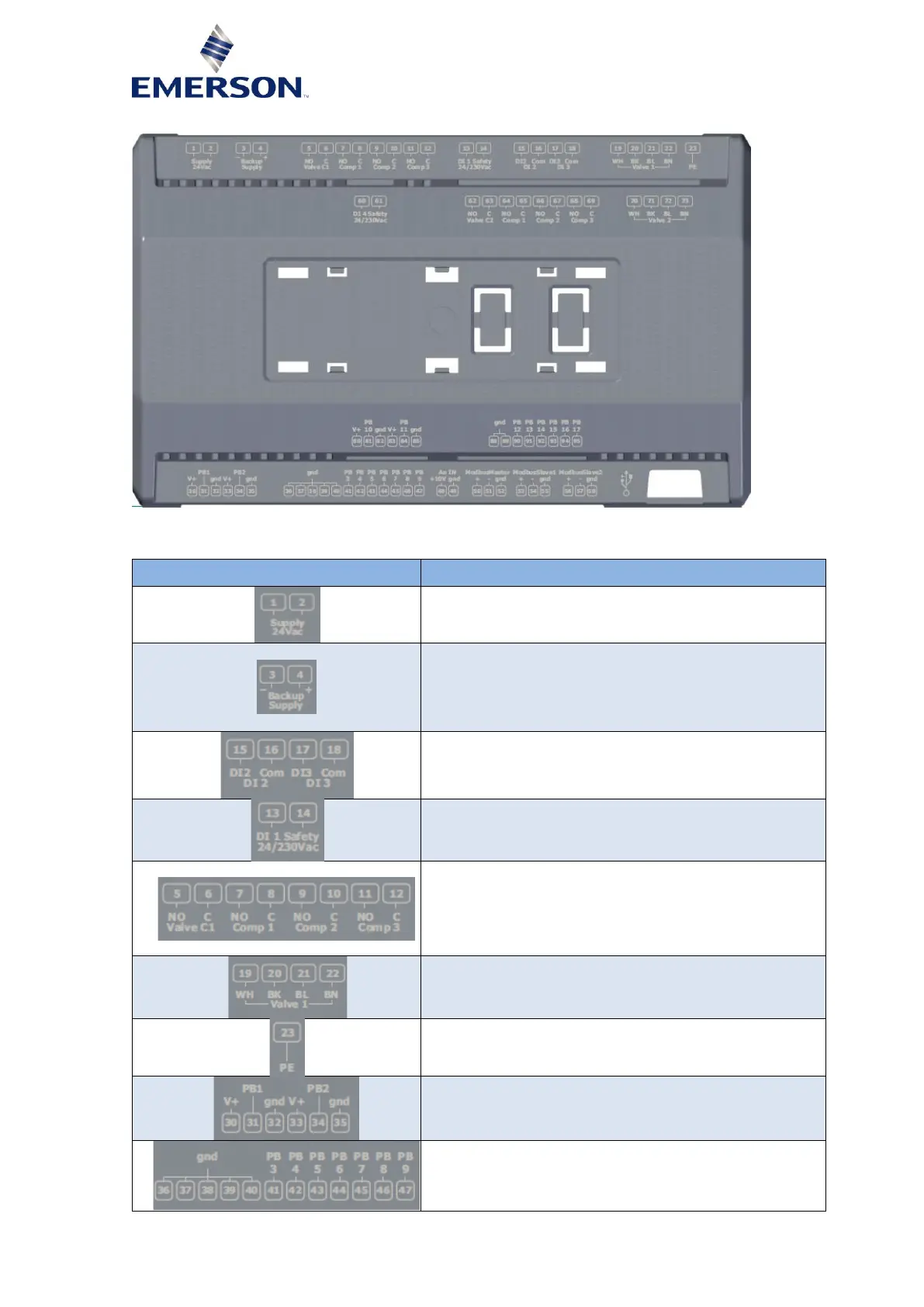
Figure 5
2.3.2.1 Description of the connections
Connector for 24 VAC/DC power supply (black colour)
Green LED to indicate the presence of power supply
Backup power supply for EXV closing in case of power
failure.
Voltage supply range (18-30 VDC) for min 10 sec.
Current requirements are dependent on number and type
of EXV.
Dry contact, potential free
24-240 Volt AC/DC, opto-isolated, feedback safety
Connector for relay:
- Relay DO1 (5-6) = 230 V~ potential free
- Relay DO2 (7-8) = 230 V~ potential free
- Relay DO3 (9-10) = 230 V~ potential free
- Relay DO4 (11-12) = 230 V~ potential free
Connector for bipolar valve circuit 1
Analog input connector
P1, P2 = 4…20 mA
Analog input connector
T1 to T7 = NTC