AGL_Sol_PEC_01_E_Rev01 11
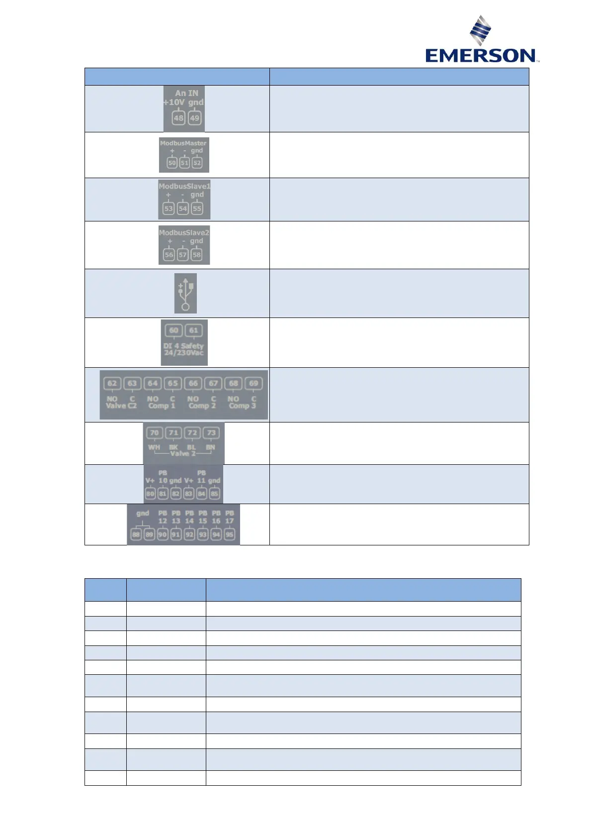
Analog 0-10 V demand signal (future use)
RS 485 connector:
- RS485 master (Modbus RTU) communication to inverter
RS485 connector, may be used for system controller
interface / monitoring
- RS485 slave (Modbus RTU)
RS485 connector, may be used for system controller
interface / monitoring or flashing
- RS485 slave (Modbus RTU)
USB port (any stick to be plugged into a PeC must be
formatted in FAT32 with 4K clusters)
24-240 VAC/DC, opto-isolated, feedback safety
(related to circuit 2)
Connector for Relay:
- Relay DO5 (62-63) = 230 V~ potential free
- Relay DO6 (64-65) = 230 V~ potential free
- Relay DO7 (66-67) = 230 V~ potential free
- Relay DO8 (68-69) = 230 V~ potential free
Connector for bipolar valve circuit 2
Analog input connector
PB10, PB11 = 4…20 mA (related to circuit 2)
Analog input connector
T8 to T17 = NTC
Table 9
2.3.2.2 Inputs and outputs description
Backup power supply (Reference "-") (18-30 VDC) for min 10 sec
Backup power supply (Reference "+") (18-30 VDC) for min 10 sec
Common relay 1 (230 VAC, max, 5 A resistive, 2 A inductive cos φ 0.5
switching capability)
Common relay 2 (230 VAC, max, 5 A resistive, 2 A inductive cos φ 0.5
switching capability)
Common relay 3 (230 VAC, max, 5 A resistive, 2 A inductive cos φ 0.5
switching capability)