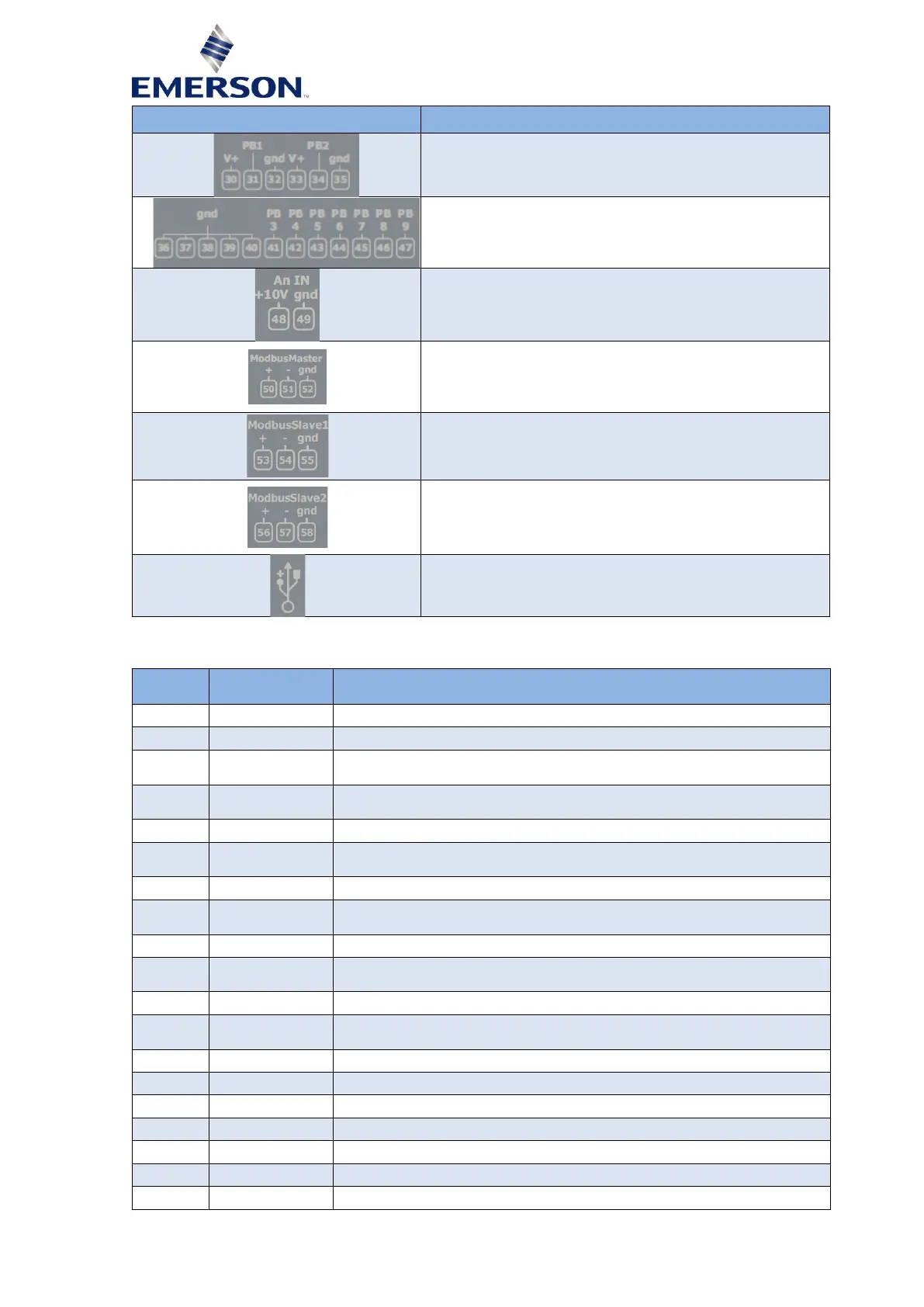
Analog input connector
P1, P2 = 4...20 mA
Analog input connector
T1 to T7 = NTC
Analog 0-10 V demand signal (future use)
RS485 connector:
- RS485 master (Modbus RTU) communication to inverter
RS485 connector, may be used for system controller interface /
monitoring
- RS485 slave (Modbus RTU)
RS485 connector, may be used for system controller interface /
monitoring or flashing
- RS485 slave (Modbus RTU)
USB port (any stick to be plugged into a PeC must be
formatted in FAT32 with 4K clusters)
Table 2
2.3.1.2 Inputs and outputs description
Input backup power supply (Reference "-") (18-30 VDC) for min 10 sec
Input backup power supply (Reference "+") (18-30 VDC) for min 10 sec
Common relay 1 (230 VAC, max, 5 A resistive, 2 A inductive cos φ 0.5
switching capability)
Common relay 2 (230 VAC, max, 5 A resistive, 2 A inductive cos φ 0.5
switching capability)
Common relay 3 (230 VAC, max, 5 A resistive, 2 A inductive cos φ 0.5
switching capability)
Common relay 4 (230 VAC, max, 5 A resistive, 2 A inductive cos φ 0.5
switching capability)
Opto-insulated digital input 1 (24-230 VAC/DC)
Opto-insulated digital input 1
Potential free digital input 2
Potential free digital input 2
Potential free digital input 3
Potential free digital input 3