Application Guide Chapter 5
GFK-2928C Oct 2019
PLC Hardware Configuration 18
Chapter 5: PLC Hardware Configuration
5.1 Overview
In general, the hardware configuration for the Primary and Secondary PLCs are very similar.
The dual-bus elements will be configured in a nearly identical manner.
5.2 PLC Reference Memory Tab Settings
In the Hardware Configuration (Primary) double-click on the RX3i CPU module to display the
configuration settings. Click on the Memory tab and adjust the upper memory limits. The
minimum settings are shown below:
Memory Settings
%AI Analog Input 16384
%AQ Analog Output 8192
%R Register Memory 32640
%W Bulk Memory 65536
Symbolic Discrete 65536
Symbolic Non-Discrete 65536
I/O Discrete 65536
I/O Non-Discrete 65536
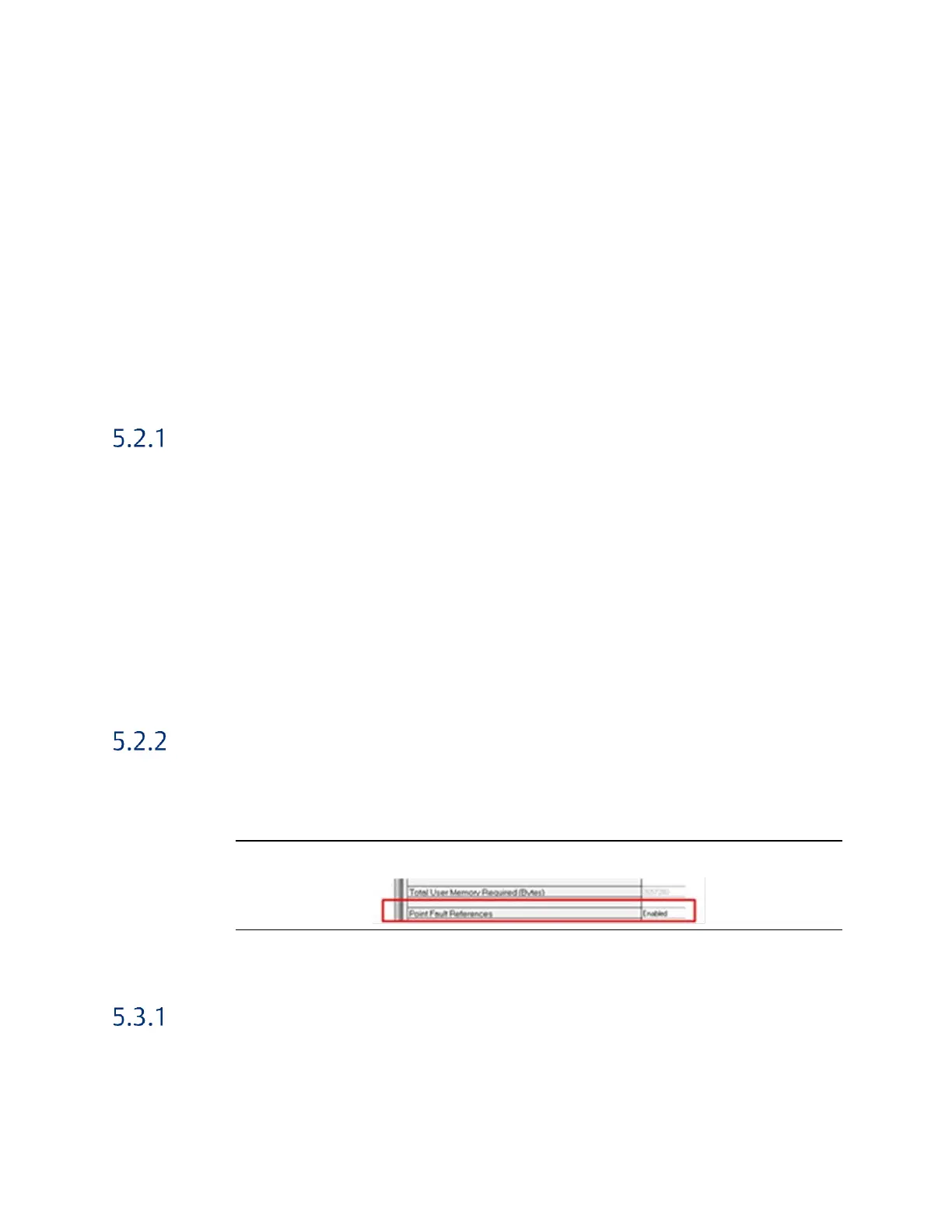
Point Fault Setting
In the Hardware Configuration (Primary) double-click on the RX3i CPU module to display the
configuration settings. Click on the Memory tab and set the Point Fault References property
to Enabled are shown below:
Figure 21: Enable Point Fault References
5.3 Transfer List Entries
Input Transfer Points
%I configured for length=0
%Q (as needed)
%M (as needed)
%G (as needed)

 Loading...


