ROC364 Instruction Manual
3-8 Input and Output Modules Rev Jun/05
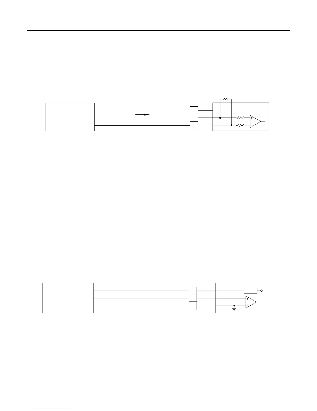
For current loop devices, scaling resistor R1 generates a voltage across terminals B and C that is
proportional to the loop current. When connecting current loop devices, the value of R1 must be selected
such that the 5-volts input limit of the module is not exceeded under maximum operating current
conditions. For 0 to 20 milliamps or 4 to 20 milliamps devices, the value of R1 would be 250 ohms. In
this case, you can use the 250-ohms (0.1%, 1/8 watt) scaling resistor supplied by the factory. The
formula for determining the value of R1 is given in Figure 3-6, where “I Maximum” is the upper end of
the operating current range, such as 0.025 amps for a 0 to 25 milliamps device.
I
TO SELECT PROPER VALUE FOR R1:
V = VOLTAGE FROM ANALOG DEVICE = 0 TO 5 VDC
SELF-POWERED
CURRENT LOOP
DEVICE
R1 =
o
V
o
+
5 VOLTS
DOC0154A
N/C
+
B
C
A
200K
200K
R1
I DIFF
Figure 3-6. AI Differential Module Field Wiring for Current Loop Devices
3.4.3 Analog Input Source Module
A schematic representation of the field wiring connections to the input circuit of the Analog Input
Source module displays in Figure 3-7 and Figure 3-8. The AI Source module normally monitors the
voltage output of low-voltage transmitters, but it can be used for monitoring loop current. The module
provides source power at terminal A for the loop. The Analog Input Source module operates by
measuring the voltage across terminals B and C. The module accepts a maximum input voltage of 5
volts dc, which is the upper operating limit of the module.
Figure 3-7 shows a typical voltage signal input. Terminal B is the positive (+) signal input and terminal
C is the negative (–) signal input. These terminals accept a voltage signal in the 0 to 5 volts range. Since
terminal C connects to common, the Analog Input can only be a single-ended input. Make sure no
scaling resistor is installed when wiring the module for a voltage signal.
VOLTAGE DEVICE
ROC-POWERED
+10Vdc
+
+10Vdc
+
C
B
A
V SRC
I SRC
Vs
SIGNAL = 0 TO 5
Figure 3-7. AI Source Module Field Wiring for Voltage Devices
The AI Source module can be used for monitoring loop current as shown in Figure 3-8. For current loop
monitoring, scaling resistor R1 generates a voltage across terminals B and C that is proportional to the
loop current (I).
 Loading...