Emerson Process Management GmbH & Co. OHG 6-73
X-STREAM XE
Instruction Manual
HASXEE-IM-HS
10/2012
6
Software Menus
6.2.3.4.4 Setup Internal SHS
6.2.3 Setup Menu
Setup..
In-/Outputs..
Internal SHS..
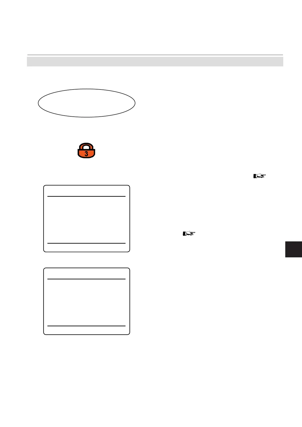
Internal SHS (2of2)
Pump1 Signal: Off
Pump2 Signal: Off
Internal SHS (1of2)
Gas1 Signal: V2
Gas2 Signal: V3
Gas3 Signal: V18
Gas4 Signal: Off
Gas5 Signal: Off
Gas6 Signal: Off
Gas7 Signal: Off
Gas8 Signal:
Off
If the system is setup accordingly, the access
code for level 3 must be entered to gain ac-
cess to this menu.
Note!
This menu appears only if your analyzer fea-
tures internal valves or pumps.
Note
Ensure that valves are assigned (
6-38 )
Each assigned valve has its label ("Gas1…
Gas8"). The current menu enables to assign
these valves (and pumps too) a signal to
control it. (If the components were installed
in the factory, the basic settings will already
have been set).
All signals applicable to digital outputs can be
used (
Tab. 6-3 at page 6-69 )
This menu enables to congure the optional
internal components for routing gas (valves
and pumps) to be used in autocalibration
procedures.
Example 1:
Gas1 Signal: Any span failed
--> The valve connected to gas inlet 1 is acti-
vated when a span calibration failure occures.
Example 2:
Gas2 Signal: V2
Pump1 Signal: V2
--> The internal signal "V2" activates the valve
connected to gas inlet 2 and pump 1.
 Loading...