15
TÜVSV ..-846
Belastung
Loading charge
Anlüftung
Liftin gr elevage
"A"
Bauteilkennzeichen:
component test mark :
Kommission:
work no .
"X"
manufact. yea r
Baujahr:
Ø9
130
11
40
Ø9
Ø15
17,5
105
85
380
1586
498498 498
415
77,5
150150
37,5°
4
Ø21,3
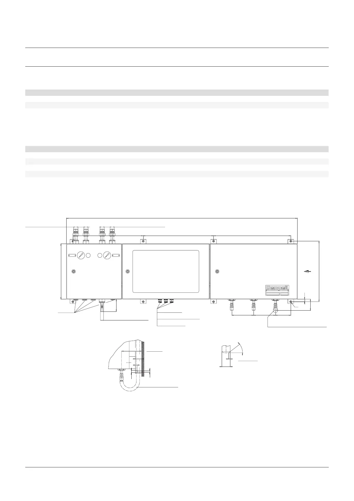
SEMPELL SERIES STE 4 CONTROL DEVICE FOR SAFETY VALVES
Operating instructiOns
9 TECHNICAL DOCUMENTS
9.1 Spare parts list
9.2 Drawings
CONTROL UNIT
SPARE PART LIST IMPULSE UNIT A161
Part no. Number of units Name of part Order no. / Dim. Manufacturer Material
A1-A3 3 Shut-off valve Sempell Div.
D1-D3 3 Pressure switch Manocomb-Sem-2K A116 Pinter Div.
P1-P3 3 Vice coupling 2103-01-44.00 Hydrotechnik Div.
SPARE PART LIST ELECTRICAL SWITCH UNIT A162
(see documentation electric switch unit)
SPARE PART LIST PNEUMATIC SWITCH UNIT A163
Part no. Name of part Order no. / Dim. Manufacturer Material
Y1-Y3 2/2 way valve 404-B-G1/2 Bürkert Div.
Y4 3/2 way valve 340-C- Bürkert Div.
MH, MB Pressure gauge 1 827 231 035 Bosch Div.
F, R Maintenance unit 354 A 052 Cubeair Div.
Air connection for
loading
Air exhaust
ø22 x 2
Main supply air connection
View “A”
View “X”
Sense line
Sense line connection
stainless steel 316
Power supply
Connection to control room
Vacant connection
Air connection for lifting
Control unit
A163
Electrical unit
A162
Pressure unit
A161