3
P5R1
Y1 Y2 Y3 F
P4 MHY4
SEMPELL SERIES STE 4 CONTROL DEVICE FOR SAFETY VALVES
Operating instructiOns
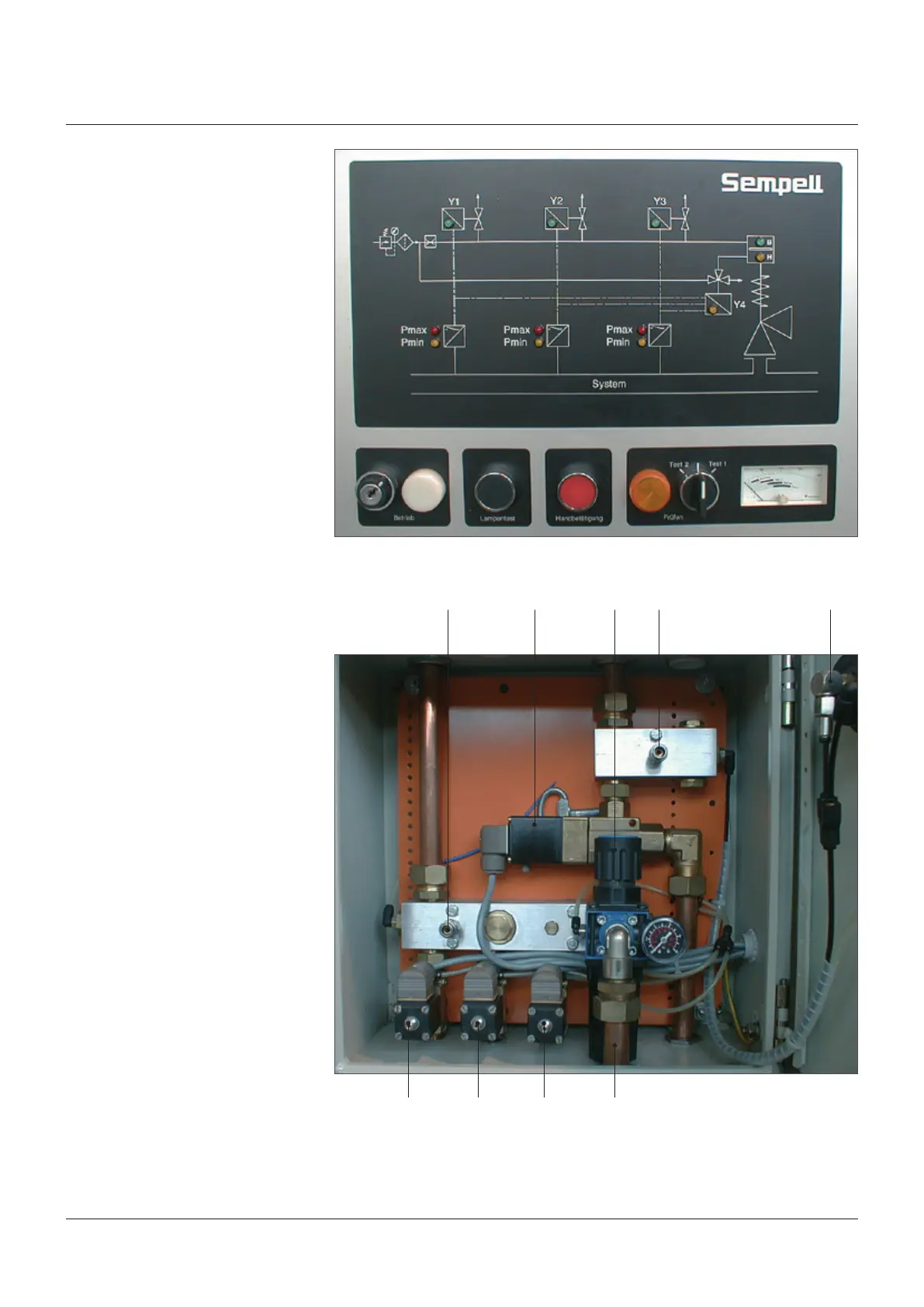
The electric switch unit includes the equipment
for signal treatment and control. At the bottom
side is the connection for the power supply.
Protected by an inspection window, control
lamps and manual switches for working and
testing are on the front panel. Pressing the
switch “Lamp Test” en ergizes all control
lamps.
The pneumatic control unit contains the
connections for the compressed-air supply
of the pneumatic section through pressure
regulator (R1) and air filter (F) to three closed-
circuit 2/2 way solenoid valves (Y1, Y2, Y3); one
open-circuit 3/2 way solenoid valve (Y4) and
the pressure gauges for loading and lifting air
(MB,MH).
At the upper side are the connections of the
control lines to the pneumatic actuator.