6
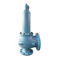
SEMPELL SERIES STE 4 CONTROL DEVICE FOR SAFETY VALVES
Operating instructiOns
• Check of the control legs 1 to 3
- Adjustment of the control air pressure to
2bar
Check of the pressure gauge “Load”
- Test switch into position “Test 1”
Signal lamp (orange) lights up.
• Check of control leg 1 (pressure switch D1,
solenoid valve Y1)
- Unlock and close shut-off valve A1.
- Slowly apply pressure to test connection P1
up to the response of the pressure switch.
Read corresponding pressure P-max at the
test gauge. Solenoid valve Y1 powerless. Drop
of the loading air; indicator at the pressure
gauge “Load” < 0.2 bar; no lifting air. Indicator
pressure gauge “Lifting” 0 bar, ampere meter
in position “Test 1”.
- Slowly drop pressure until the pressure
switch switches back.
Read corresponding pressure P-min at the
test gauge. Solenoid valve Y1 is energized and
closes. Loading air will be charged. Indicator
pressure gauge “Load” 2 bar.
- Open and lock shut-off valve A1.
• Check of control leg 2 (pressure switch D2,
solenoid valve Y2)
- Unlock and close shut-off valve A2.
- Slowly apply pressure to test connection P2
up to the response of the pressure switch.
Read corresponding pressure P-max at the
test gauge. Solenoid valve Y2 powerless. Drop
of the loading air; indicator at the pressure
gauge “Load” < 0.2 bar; no lifting air. Indicator
pressure gauge “Lifting” 0 bar, ampere meter
in position “Test 1”.
- Slowly drop pressure until the pressure
switch switches back.
Read corresponding pressure P-min at the
test gauge. Solenoid valve Y2 is energized and
closes. Loading air will be charged. Indicator
pressure gauge “Load” 2 bar.
- Open and lock shut-off valve A2.
• Check of control leg 3 (pressure switch D3,
solenoid valve Y3)
- Unlock and close shut-off valve A3.
- Slowly apply pressure to test connection P3
up to the response of the pressure switch.
Read corresponding pressure P-max at the
test gauge. Solenoid valve Y3 powerless. Drop
of the loading air; indicator at the pressure
gauge “Load” < 0.2 bar; no lifting air. Indicator
pressure gauge “Lifting” 0 bar, ampere meter
in position “Test 1”.
- Slowly drop pressure until the pressure
switch switches back.
Read corresponding pressure P-min at the
test gauge. Solenoid valve Y3 is energized and
closes. Loading air will be charged. Indicator
pressure gauge “Load” 2 bar.
- Open and lock shut-off valve A3.
• Set back to working conditions
- Turn test switch into position “Operation”.
Set control air pressure at normal operating
pressure.
Signal lamp (orange) goes out. Control at the
pressure gauge “Load”.
4.7.2 Check of the displacement force reserve of
solenoid valves Y1, Y2 and Y3
The solenoid valves (Y1, Y2, Y3) consist of a
electric actuated pilot valve and a pneumatic
actuated control valve.
At the electric actuated pilot valve, pressing the
respective push-button in the electric switch
unit lowers the operating tension up to a value
where a faultless solenoid has to switch. A
pressure drop of the loading air at the pressure
gauge (MB) shows the switching. The lifting air
is not actuated.
As the extent of the loading air pressure
counteracts the switch safety of the solenoid
valve check with the highest possible control
pressure.
By means of the magnetic actuated pilot valve
the pilot pressure is released. In case of the
pneumatic actuated control valve the height of
the air pressure brings about the switch safety.
To prove the displacement force reserve on the
control valve check with the lowest possible
control pressure (operation test according to
section 4.7.1).
Control the displacement force reserve at the
solenoid valves by pressing the switches at
a highest possible air pressure. Afterwards
control according to section 4.7.1 at lowered air
pressure.
The loading air pressure has to drop
top<0.2bar for all tests.
Once a year an inspector has to test the
displacement force reserves with the same
pressures.
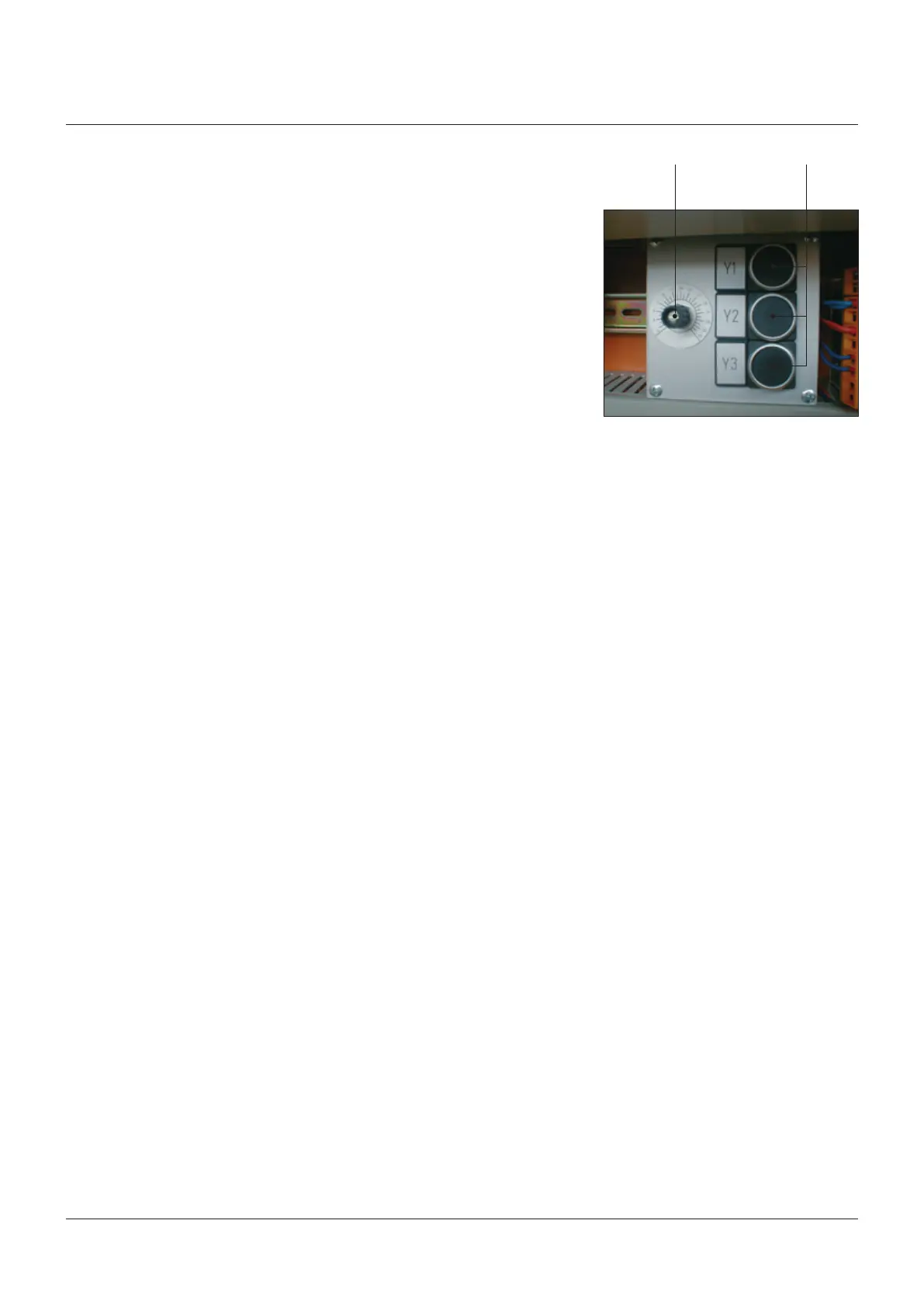
Potentiometer Switch