9
SEMPELL SERIES STE 4 CONTROL DEVICE FOR SAFETY VALVES
Operating instructiOns
The pneumatic actuator is temporarily switched
off; the safety valve remains fully operational.
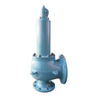
• In case of a cup spring safety valve
(type VSE8, SOT) unscrew the cap of the
pneumatic actuator and attach test cap with
displacement pickup to the safety valve.
• For a safety valve (VSE/VSR 1/5, SO, SB) with
mounted pneumatic actuator A160 assemble
the displacement pickup sideways to the
coupling.
• Connect pressure transmitter to lifting air (P5
in the pneumatic control unit). Also connect a
pressure transmitter to the system pressure.
• Press and hold fast hand actuation. Slowly
turn up handwheel of the pressure regulator
R1 (clockwise rotation). The pressure gauge
“Lifting” indicates the increasing lifting air
pressure. Increase pressure until the safety
valve opens. Measure and register pressure
and lift with the help of the measuring
devices.
• After finishing the opening loosen hand
actuation. The lifting air will be reduced and
the loading air will be built up again.
• The safety valve closes.
• At a pneumatic control unit equipped with an
additional pressure block valve for the lifting
air (e.g. for drum valves), it shall be actuated
additional to the switch “Hand Lifting”.
After finishing the test restore the original
control pressure again.
It is also possible to remove and shut the
control air hoses at the second safety valve.
Procedures
• Re-adjust control pressure at the pressure
regulator R1 to the previously registered
value by moving up and turning clockwise the
regulator handle. Read the pressure at the
pressure gauge. Moving down the regulator
handle secures the adjustment.
Notice! In case of two or several safety valves
controlled by one control unit, all safety valves
open at the procedure described above. If only
the tested safety valve shall open, it is possible
to block the second safety valve mechanically
under consideration of special precautions.
After finishing the test, remove this safety valve
blocking in any case!!!
5 TASKS OF THE INDEPENDENT INSPECTOR
These tasks are executed according to VdTÜV
Merkblatt SV ..-846.
5.1 At inspection test
Before commissioning
1. Check correspondence of approved type test
identification number with the mark on the
control unit.
5.2 At periodic inspections
1. Check external state.
2. Yearly check control device according to
section 5.1, point 4.
3. Yearly check the adjustment of the main
valve without loading and lifting air
(seesection4.7.6).
4. Yearly check operation of the main valve.
To evaluate the lifting course against time
execute the test with system pressure and
capacity comparable to the first test.
5. Check sliding faces at spindle, pistons,
guides and so on in contact with medium in
regard of defects. Examine welding seams
and greater wall interface thickness in
regard of cracks.
2. Check reliability of the main valve in
connection with the control device.
3. Check correspondence of functional
diagram with the design.
4. Check each control leg according to
section4.7.1-3.
In doing so, especially check the adjustment
of the pressure switch, the displacement
force reserve and the reduction of the
air. The time to reduce air shall be about
the same for each control leg. Therefore
register the pressure in- and decrease of
lifting and loading air against time. The dead
time of the control device must correspond
to the pressure change rate of the protected
system.
During operation of the system
1. Shut off air. Check the adjustment of the
main valve without loading and lifting air.
Register lift of the main valve and the
system pressure against time. When the
main valve only opens to some extent due
to operation, check by extrapolation of the
lift course if the required lift is reached at
least at 10% above the admissible design
pressure. If the safety valve has capacity
reserves, the maximum possible lift for
discharging the required discharge amounts
must not be reached. This test is not
necessary for type-tested safety valves.
2. Fully open the main valve with the lifting air.
Check movability. This can also be executed
by hand through the manual switch at
operational pressure. Register system
pressure, air lifting pressure and lift of the
main valve against time.
3. The admissible ambient temperature of
60°C must not be exceeded at the position
of the electric components of the control
device.