January 2001
Installation, Operation and Maintenance Manual
PBC-01102001 Rev. A
6
Section 1: Introduction
Introduction
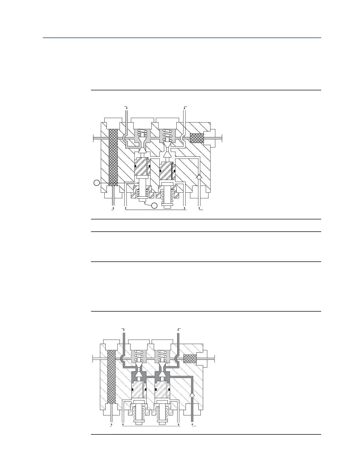
Movement of the lever (7) illustrates force applied by the stem (6), seating the exhaust
poppet and simultaneously unseating the power poppet. Power gas is directed through
tank port "A".
Figure 4 Manual Activation
TANK “A”
POWER PILOT
EXHAUST OR
RETURN OIL
TANK “B”
6
7
NOTE:
Movement of the opposite lever shown in Figure 4 will activate the opposite set of poppets
and direct power gas to tank port "B".
Release of the lever will allow the compressed poppet spring and power gas to reseat the
power poppet and simultaneously unseat the exhaust poppet. Power gas pressure
remaining in the gas/hydraulic tank is now vented through port "B" to the exhaust, thus
neutralizing tank and actuator pressures.
Figure 5 Neutralization
TANK “A”
POWER PILOT
EXHAUST OR
TANK “B”
 Loading...


