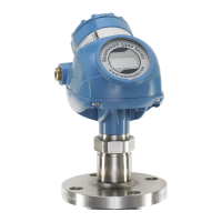
Do you have a question about the Emerson Rosemount and is the answer not in the manual?
Provides an overview of the manual's purpose and structure.
Details the key features and capabilities of the Rosemount 3144P transmitter.
Covers electrical installation requirements for proper operation and noise prevention.
Provides guidance on selecting installation locations and positions for the transmitter.
Explains how to confirm HART capability of systems before transmitter installation.
Lists safety precautions for personnel performing operations.
Outlines the process of testing and verifying transmitter configuration data.
Explains how to set the process application loop to manual mode.
Provides instructions for setting transmitter switches for HART and FOUNDATION fieldbus.
Offers recommendations for mounting the transmitter to prevent moisture ingress.
Provides guidance on installing the transmitter.
Details the steps for a typical North American installation.
Describes the procedure for a typical European installation.
Covers the installation of the LCD display option on the transmitter.
Provides instructions for wiring the transmitter.
Provides instructions for field wiring the transmitter for HART/4-20mA communication.
Details wiring diagrams for FOUNDATION fieldbus configurations.
Explains correct sensor wiring connections to the transmitter terminals.
Specifies power supply requirements for HART and FOUNDATION fieldbus transmitters.
Introduces commissioning tasks performed before installation.
Explains how to confirm HART capability of systems and transmitters.
Lists safety precautions for HART commissioning operations.
Explains how the field communicator exchanges information with the transmitter.
Guides on determining if field communicator software needs an upgrade.
Covers basic variable configuration for transmitter operation.
Explains configuring the transmitter to use Sensor 2 if Sensor 1 fails.
Allows setting a warning flag or analog alarm for temperature differences between sensors.
Covers PV range values, alarm/saturation, HART output, and LCD display options.
Lists diagnostic and service functions available after field installation.
Introduces advanced diagnostic features like Thermocouple Degradation.
Monitors thermocouple loop health and detects drift or wiring issues.
Explains how calibrating increases measurement system precision.
Describes trim functions for adjusting the transmitter's interpretation of sensor input.
Allows altering the transmitter's interpretation of the input signal.
Generates a custom curve to match sensor resistance vs. temperature performance.
Provides guidance for troubleshooting suspected malfunctions.
Lists safety precautions for FOUNDATION fieldbus operations.
Includes sensor data, engineering units, linearization, and diagnostics.
Explains configuring the AI block with parameters like Channel, L_TYPE, XD_SCALE.
Covers configuring alarm limits and priorities for process alarms.
Explains trim functions to adjust the transmitter's sensor interpretation.
Provides a flowchart for troubleshooting communication problems.
Lists safety precautions for maintenance operations.
Discusses scheduled maintenance and modular design for easy service.
States the transmitter's certification for safety instrumented systems per IEC61508.
Lists safety precautions for personnel performing operations in this section.
Details IEC61508 certification levels for single and redundant transmitters.
Recommends proof tests and documentation for safety functionality.
Recommends proof tests and documentation for safety functionality.
Lists specifications for stability, vibration effect, self-calibration, RFI effect, and CE compliance.
| Category | Industrial Equipment |
|---|---|
| Manufacturer | Emerson |
| Product Type | Pressure Transmitter |
| Output Signal | 4-20 mA HART, FOUNDATION Fieldbus |
| Process Connection | 1/2" NPT, 1/4" NPT |
| Electrical Connection | 1/2" NPT |
| Operating Temperature | -40°C to 85°C (-40°F to 185°F) |
| Environmental Rating | NEMA 4X, IP66 |


