152
Reference Manual
00809-0100-4021, Rev GC
Section 4: FOUNDATION fieldbus Configuration
April 2014
Foundation™ fieldbus configuration
4.7 LCD display transducer block
The LCD display connects directly to the 3144P electronics FOUNDATION fieldbus output board.
The meter indicates output and abbreviated diagnostic messages.
The first line of five characters displays the sensor being measured.
If the measurement is in error, “Error” appears on the first line. The second line indicates if the
device or the sensor is causing the error.
Each parameter configured for display will appear on the LCD display for a brief period before the
next parameter is displayed. If the status of the parameter goes bad, the LCD display will also
cycle diagnostics following the displayed variable:
4.7.1 Custom meter configuration
Parameter #1 (Sensor 1) is factory configured to display the Primary Variable (temperature)
from the LCD display transducer block. When shipping with dual sensors, Sensor 2 will be
configured not to display. To change the configuration of Parameter #1, #2, or to configure
additional parameters use the configuration parameters below. The LCD display Transducer
Block can be configured to sequence four different process variables as long as the parameters
are sourced from a function block scheduled to execute within the 3144P temperature
transmitter. If a function block is scheduled in the 3144P that links a process variable from
another device on the segment, that process variable can be displayed on the LCD display.
DISPLAY_PARAM_SEL
The DISPLAY_PARAM_SEL specifies how many process variables will be displayed, where up to
four display parameters can be selected.
BLK_TAG_#
(1)
Enter the Block Tag of the function block containing the parameter to be displayed. The default
function block tags from the factory are:
TRANSDUCER
AI 1400, 1500, 1600, 1700
PID 1800 and 1900
ISEL 2000
CHAR 2100
ARTH 2200
Output Splitter OSPL 2300
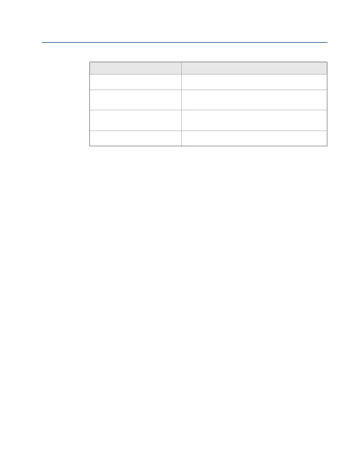
Terminal (Body) Temperature Out of
Operating Range
PRT readings have gone beyond SECONDARY_VALUE_RANGE
values
Terminal (Body) Temperature Beyond
Operating Limits
PRT readings have gone below 2% of lower range or above 6%
of upper range of PRT. (These ranges are calculated and are
not the actual range of the PRT which is a PT100 A385)
Sensor Degraded For RTDs, this is excessive EMF detected.
For Thermocouples, the loop resistance has drifted beyond
the user-configured threshold limit.
Calibration Error The user trim has failed due to excessive correction or sensor
failure during the trim method
(1) # represents the specified parameter number.
Table 4-7. Sensor Transducer Block STB.SENSOR_DETAILED_ STATUS messages
STB.SENSOR_DETAILED_STATUS Description