Do you have a question about the Emerson Micro Motion ELITE and is the answer not in the manual?
Introduction to the Micro Motion ELITE sensor as part of a Coriolis flowmetering system.
Details two transmitter connection types: integral core processor and 9-wire junction box.
Information on product compliance with European directives and ATEX documentation.
States that sensor components are illustrated in this section.
Illustrations and labels for CMF010 sensor with junction box and core processor.
Illustrations for CMF025, CMF050, CMF100 sensors with junction box and core processor.
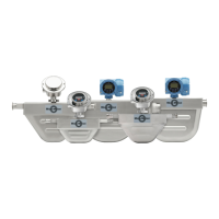
Illustrations for CMF200 and CMF300 sensors with junction box and core processor.
Illustration of CMF300A sensor with its remote-mount junction box.
Illustration of CMF400 sensor with integral booster amplifier and core processor.
Illustration of CMF400 sensor with remote booster amplifier and core processor.
Illustration of CMF400 sensor with integral booster amplifier and junction box.
Determining proper sensor location, considering hazardous areas, piping, and valves.
Determining the desired orientation for the sensor in the process pipeline.
Installing the sensor in the pipeline.
Connecting the flowmeter cable to the sensor and transmitter.
Requirements for flowmeter startup.
Lists troubleshooting topics covered in the manual, starting on page 45.
Details on purge fittings described in Appendix A, page 59.
Details on rupture disks described in Appendix B, page 63.
Explanation of label maintenance in Appendix C, page 65.
Conditions and considerations for selecting sensor location.
Guidelines for sensor placement in relation to upstream and downstream piping.
Table detailing maximum cable lengths based on cable type and gauge.
Specifies acceptable process fluid and ambient temperature ranges for sensor installation.
Conditions for proper sensor function regardless of orientation.
How the flow direction arrow aids transmitter configuration.
Recommendations for liquid/slurry flow direction in vertical installations.
Instructions on rotating core processor or junction box for conduit orientation.
Piping practices to minimize torque and bending load on process connections.
General illustration showing how to mount an ELITE sensor in a pipeline.
Methods for mounting the CMF010 sensor, including using bolts.
Procedure for installing wafer-style sensors using flange bolts and alignment rings.
Warnings and guidelines for wiring in hazardous areas.
Wiring notes for CMF400 sensor, including booster amplifier and remote connections.
Requirements for wiring the CMF400 booster amplifier to an AC power supply.
Grounding and sealing precautions for CMF300A junction box.
Procedure to establish flowmeter response to zero flow and set baseline.
Explanation of configuration, calibration, and characterization parameters.
Information on contacting Micro Motion Customer Service for startup assistance.
Overview of troubleshooting resources and topics covered in the manual.
Guidance for troubleshooting issues at the transmitter level.
Guidance on identifying and addressing vibration or crosstalk issues.
Causes and identification of two-phase flow in process streams.
Instructions on maintaining the seal of purge fittings and case purging.
Warnings and instructions for removing and re-purging the sensor case.
Detailed steps for purging the sensor case with dry inert gas.
Importance of keeping rupture disks installed and re-purging the case if removed.
Warnings and instructions for removing rupture disks and re-purging the case.
Illustration of ELITE sensor safety label with purge fittings.
Illustration of CMF010 sensor safety label with rupture disks.
Illustration of caution label inside core processor housing.
Illustration of intrinsically safe connections label.
Procedures for returning equipment and meeting DOT regulations.
Definition of new/unused equipment and conditions for return.
Requirements for returning used equipment, including decontamination.
List of troubleshooting topics and their corresponding page numbers.
List of installation steps and related page references.
| Brand | Emerson |
|---|---|
| Model | Micro Motion ELITE |
| Category | Industrial Equipment |
| Language | English |