ER5000 —
66
Getting Started
Connect and verify the power supply (cont.)
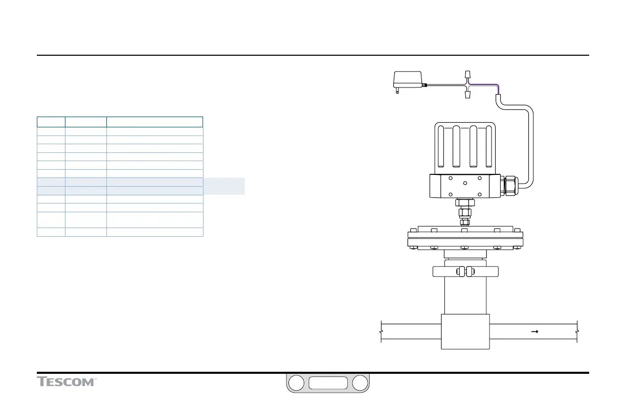
1. Refer to Table 2 below and Figure 9 to verify correct wiring.
Table 2: Main Cable Wiring for Power Supply
J3 Pins Wire Color Function
1 brown +setpoint input
2 red -setpoint input
3 orange +feedback input
4 yellow -feedback input
5 green -RS485 network connection
6 blue +RS485 network connection
7 violet +24V DC power
Standard
Installation
8 gray 24V return (power ground)
9 white +5V output (5 mA max.)
10 black analog signal/board ground
*11 *pink analog signal output
(active in Enhanced “F” models ONLY)
12 tan analog signal/board ground
2. For standard model ER5000s, the 12-pin MTA connector comes pre-installed
to the J3 terminal block. For “F” model ER5000s, the standard 12-pin MTA
connector and auxiliary 8-pin MTA connector come pre-installed to the J3 and
J4 blocks.
3. Connect the violet wire (Pin 7) to the +24V DC wire from the power supply.
4. Connect the gray wire (Pin 8) to the ground wire from the power supply.
5. Plug in the power supply.
(continued next page)
Power
Supply
+24V DC
VIOLET
GRAY
Controller
Supply Pressure
To Process
Regulator
GROUND
Adaptor
Figure 9: Connect the ER5000 to the Power Supply

 Loading...

