6 Wiring diagrams
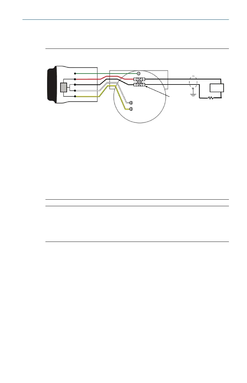
Figure 6-1: Direct Mount Wiring Diagram for 2-Wire Device
A
Green
Red
Black
White
Yellow
4 -20 mA Loop +
4 -20 mA Loop -
B
C
D
E
F
- PWR/COMM
+ PWR/COMM
A. THUM Adapter
B. Wired device
C. Ground
D. Splice connector
E. Load resistor ≥ 250 W
F. Power supply
Note
In order for the THUM Adapter to function properly there must be at least
250 Ohms resistance in the loop. If the 4–20 mA loop does not have the
required resistance, wire a resistor as shown in Figure 6-3,Figure 6-7, or
Figure 6-11 as applicable.
September 2020 Quick Start Guide
Quick Start Guide 11