8 Unidrive M700/M701 / Unidrive HS70/HS71 Control Getting Started Guide
Issue Number: 2
3 Control connections
3.1 Position feedback connections
The following functions are provided via the 15-way high density D-type connector on the drive:
• Two position feedback interfaces (P1 and P2).
• One encoder simulation output.
• Two freeze trigger inputs (marker inputs).
• One thermistor input.
The P1 position interface is always available but the availability of the P2 position interface and the
encoder simulation output depends on the position feedback device used on the P1 position interface.
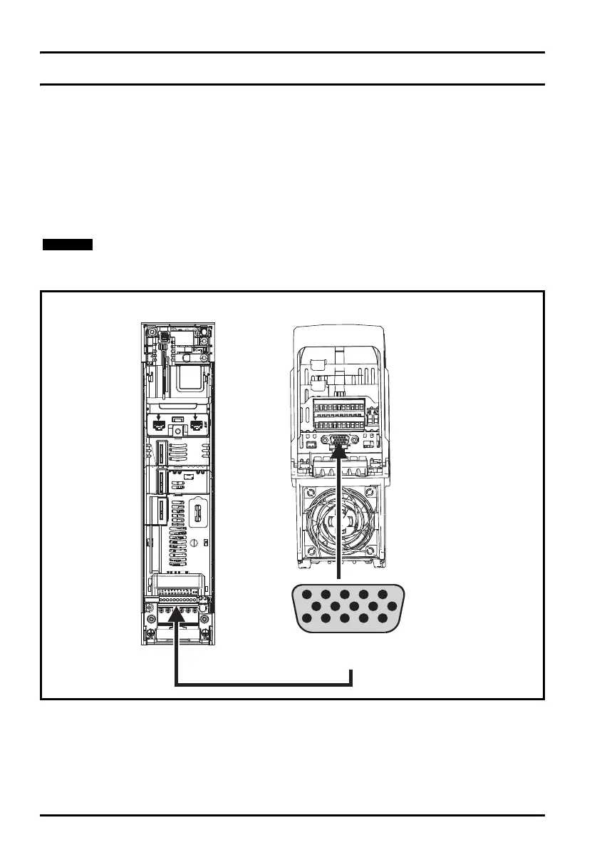
Figure 3-1 Location of position feedback connection
Refer to the Drive User Guide for information regarding the supported feedback devices
on the P1 and P2 position interface and the encoder stimulation output.
5
10
15
1
6
11
Drive encoder connector
Female 15-way D-type
Front view
End view
Unidrive M700_M701 Getting Started Guide English iss7.book Page 8 Friday, December 12, 2014 1:14 PM
 Loading...


