148 SI-Ethernet User Guide
Issue: 1
7.5.7 Configuring the PLC
Due to the many different makes of PLCs available, the information in this section may
not be relevant to all types of PLCs. The information supplied in this section relates to
the “ControlLogix” family of controllers supplied by “Allen Bradley”.
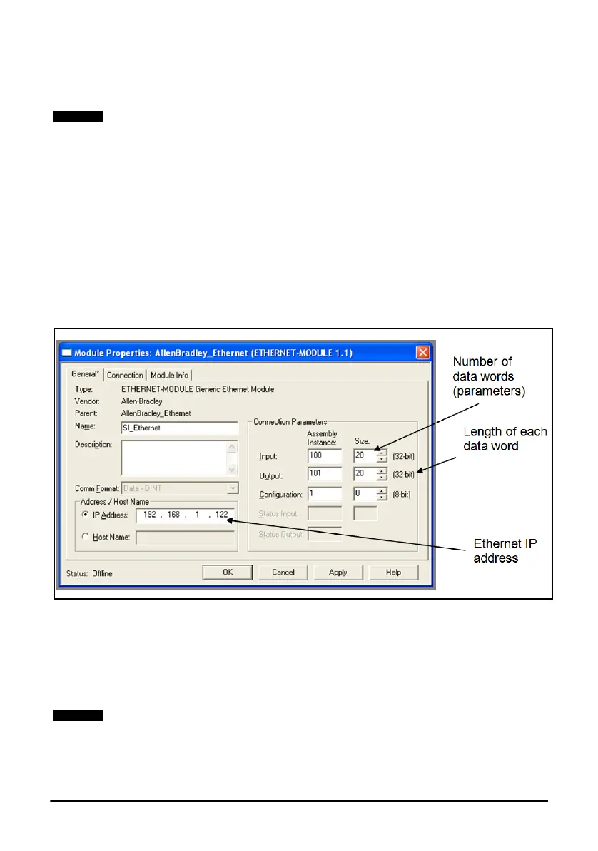
When configuring the PLC for cyclic communication with Unidrive M, the length of each
parameter data word and the number of parameters must be specified correctly, Figure
7-5, shows the PLC configuration for 20 input parameters and 20 output parameters, as
each parameter consists of 32 bits (4 bytes), the length of each data word should be set
to 32 bits (DINT - double integer word).
The length of each data word must normally be configured when the Ethernet module is
created within the PLC and can not be changed. If a different length is required then a
new Ethernet module must be created.
In order to communicate with the Unidrive M, the PLC must have the Ethernet IP
address set correctly as illustrated in Figure 7-5.
Figure 7-5 PLC configuration
7.5.8 Assembly objects
An assembly object is an object which contains a group of attributes to control or
monitor the drive operation. These attributes can be members of EtherNet/IP objects or
drive parameters. The Ethernet interface supports a series of standard assembly
objects and two Control Techniques objects (100 and 101) to access the drive
parameters (see Table 7.8 Supported drive assembly objects on page 149).
Although the Allen Bradley PLCs are mentioned in this document, this does not repre-
sent an endorsement of any particular PLC type or PLC manufacturer.
Conformance with the pre-defined assembly objects specification can only be guaran-
teed if the speed reference configuration of the drive has not been changed from the de-
fault settings. For information on setting default values, refer to the appropriate drive user
guide.

 Loading...


