154 SI-Ethernet User Guide
Issue: 1
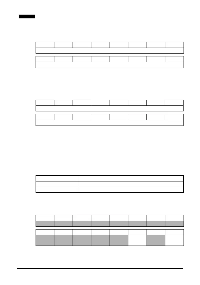
Speed reference (SpeedRef)
The speed reference word utilises 2 bytes (16 bits) as shown below.
For more information on the setting of the speed reference see section 7.31 AC/DC
Drive object attributes on page 174.
Torque reference (TorqueRef)
The torque reference word utilises 2 bytes (16 bits) as shown below.
For more information on the setting of the torque reference see section 7.31 AC/DC
Drive object attributes on page 174.
7.5.13 Basic speed feedback
Input assembly object 0x46 (70
10
)
The PLC or scanner must be configured for 4 input bytes (or 2 input words) if this
assembly object is to be used.
Basic status word
The basic status word consists of 2 bytes (16 bits), with only 2 bits of the low byte used
as shown below.
For information on the drive control word see Table 7.10 Drive control word bit
functions on page 150.
b15 b14 b13 b12 b11 b10 b9 b8
SpeedRef (high byte)
b7 b6 b5 b4 b3 b2 b1 b0
SpeedRef (low byte)
b15 b14 b13 b12 b11 b10 b9 b8
TorqueRef (high byte)
b7 b6 b5 b4 b3 b2 b1 b0
TorqueRef (low byte)
Table 7.14 Basic speed feedback
Data word Function
Word 0 Basic status word.
Word 1 Speed feedback (SpeedActual).
b15 b14 b13 b12 b11 b10 b9 b8
b7 b6 b5 b4 b3 b2 b1 b0
Running1
(Fwd)
Faulted

 Loading...


