Do you have a question about the Emerson XR75CX and is the answer not in the manual?
Safety precautions and warnings for using the manual and the device.
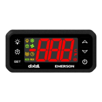
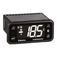
Overview of the XR75CX controller's features and applications.
Details on different XR75CX models and their Emerson codes.
Regulation of the compressor based on temperature and setpoint.
Details on defrost modes, intervals, and duration control.
Modes and parameters for controlling evaporator fans, including forced and cyclical activation.
Configures the auxiliary relay for various functions like light, alarm, or thermostat.
Description of the functions of each key on the XR75CX controller's front panel.
Explanation of the meaning of each LED indicator on the controller.
Steps to view the minimum recorded temperature.
Steps to view the maximum recorded temperature.
Procedure to reset the stored maximum and minimum temperatures.
Instructions for setting the current time and day on devices with RTC.
Procedure to display the current setpoint value.
Steps to modify the controller's setpoint value.
Initiating a manual defrost cycle using the DEF key.
Guide to entering programming mode and changing parameter values.
Introduction to the hidden menu containing all controller parameters.
Procedure for assigning a MODBUS address to the controller.
Steps to lock the controller's keyboard to prevent unauthorized changes.
Procedure to unlock the controller's keyboard.
Explanation of how to activate and manage the continuous cycle function.
How to use the ON/OFF key to control the device's operation.
Configuration for generic alarm triggered by a digital input.
Setting up a serious alarm mode activated by a digital input.
Functionality of the pressure switch input and its alarm conditions.
How the door switch input signals door status and triggers alarms.
Using a digital input to initiate a defrost cycle.
Using a digital input to switch the auxiliary relay's status.
Inverting the controller's regulation between heating and cooling modes.
Enabling the energy saving function via a digital input.
Enabling the holiday defrost setting through a digital input.
Using a digital input to switch the controller ON and OFF.
Configuration of digital input polarity based on i1P and i2P parameters.
Recommendations for correctly connecting the temperature probes.
Procedure to upload controller configuration to a Hot Key.
Procedure to download configuration from a Hot Key to the controller.
How to silence the buzzer and alarm relay output.
How alarms recover after the fault condition is resolved.
Explanation of additional display messages shown by the controller.
Steps to set up ports and configure devices for Modbus networking on E2.
Configuring E2 ports for Modbus communication.
Adding and addressing XR75CX units to the E2 network.
Recommended cable types and specifications for Modbus network wiring.
Using MODBUS termination blocks for proper network termination.
| Brand | Emerson |
|---|---|
| Model | XR75CX |
| Category | Controller |
| Language | English |