4 • XR75CX I&O Manual 026-1210 Rev 0 09-FEB-2011
4 Front Panel
Commands
4.1. Keys and Functions
Table 4-1 shows the keys that are found on the
front panel of the XR75CX controller and their corre-
sponding functions:
4.2. Use of LEDS
Each LED function is described in Table 4-2:
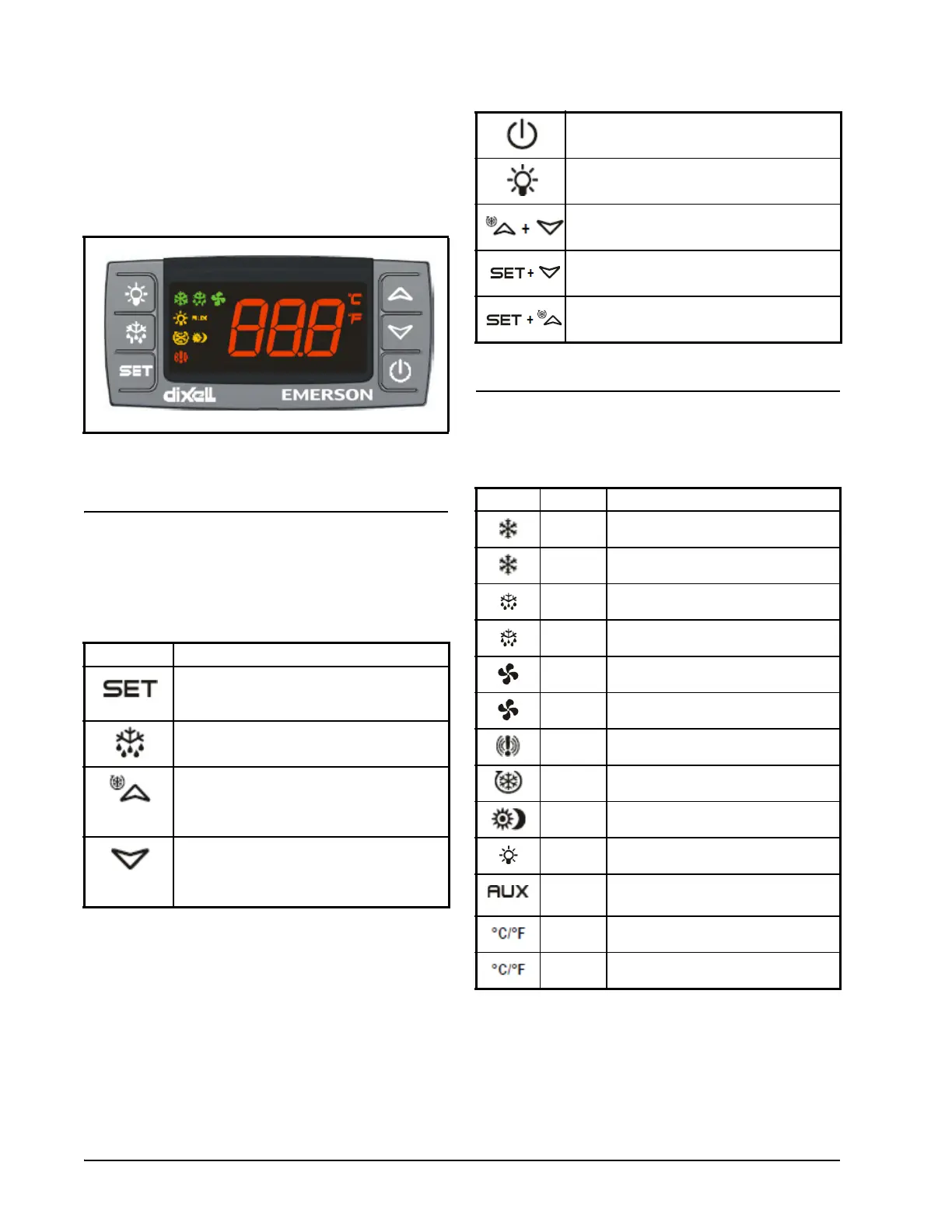
Figure 4-1 - XR75CX Front Panel
Key Function
Press to display target setpoint, to select a pa-
rameter in programming mode, or to confirm
an operation
Starts a manual defrost
Press the UP arrow to see the MAX tempera-
ture, to browse the parameter codes in pro-
gramming mode, or to increase the currently
displayed temperature value.
Press the DOWN arrow to see the MIN tem-
perature, to browse the parameter codes in
programming mode, or to decrease the cur-
rently displayed temperature value.
Table 4-1 - XR75CX Front Panel Keys and Functions
Switches the device ON and OFF, if
onF = oFF
Switches the light ON and OFF, if oA1 = Lig
Locks/Unlocks the keyboard
To enter programming mode
Returns to room temperature display
LED Mode Function
ON Compressor enabled
Flashing Anti-short cycle delay enabled
ON Defrost enabled
Flashing Drip time in progress
ON Fans enabled
Flashing Fans delay after defrost in progress.
ON An alarm is occurring
ON Continuous cycle is running
ON Energy saving enabled
ON Light ON
ON30 Auxiliary relay ON
ON Measurement unit
Flashing Programming phase
Table 4-2 - LEDs
Table 4-1 - XR75CX Front Panel Keys and Functions

 Loading...