Wiring Types ECT MODBUS Networking to E2s • 25
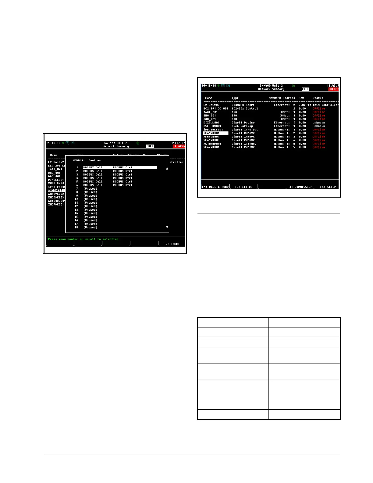
choose the address number corresponding to
the XR75CX address set up through the front
display, and press
to select it. A win-
dow will open where you can specify the ad-
dress of the controller. If a network ID has
already been selected, its name will be shown
next to the network ID in this list. If the net-
work ID you are trying to assign has already
been used, you must set the address on this
device to a different number that is not being
used.
7. Repeat Steps 5 and 6 until each device has a
name and address.
8. When finished, press
to return to the
Network Setup menu, then press
- Net-
work Summary (Figure 18-5). Locate the
devices you set up, and look at each device’s
status in the Status field. You will see one of
the following messages:
• Online - The device is communicating normally.
• Offline - The device is not communicating, has not
been commissioned, is not functional, or is not pow-
ered up. Verify the device is powered up, wired cor-
rectly, and has the proper network address, baud
rate, and parity.
• Unknown - The device is not communicating or has
not been commissioned. Verify the device is pow-
ered up, wired correctly, and has the proper network
address, baud rate, and parity.
• No Port - No port is set up in the E2 Serial Config-
uration Manager to be a MODBUS port.
• Wrong FW Rev - This message is likely caused by
the device having a firmware version older than the
minimum revision required by E2 for communica-
tion. Replace the device with a new one or a device
that has the latest version of firmware on it.
18.2.Wiring Types
Retail Solutions specifies Belden #8761 shielded
twisted pair cables for use as MODBUS wiring (or
Belden #82761 and Belden #88761 for plenum instal-
lations).
For MODBUS network wiring of XR75CX con-
trollers to E2, Belden #8641 (CPC P/N 135-8641) is
the recommended wire type to use.
If the recommended cable is not available in your
area, be sure the wiring meets or exceeds the follow-
ing specs:
Figure 18-6 - List of MODBUS Devices
Figure 18-7 - Network Summary Screen
Shielded? Yes
Conductor Type Twisted Pair
Gauge 18 - 24 AWG
Capacitance between
signal wires
31 pF/ft or less
(9.45 m) or less
Capacitance between
signal and shield
59 pF/ft or less
(17.98 m) or less
Maximum Length 4000 ft/18 to 22 AWG
(1219.2 m)
2500 ft/24 AWG
(762 m)
Nominal Impedance 120W±50W

 Loading...