www.enviromaster.com
15
Cassette Air Handler
High Volt Electrical Wiring - Continued
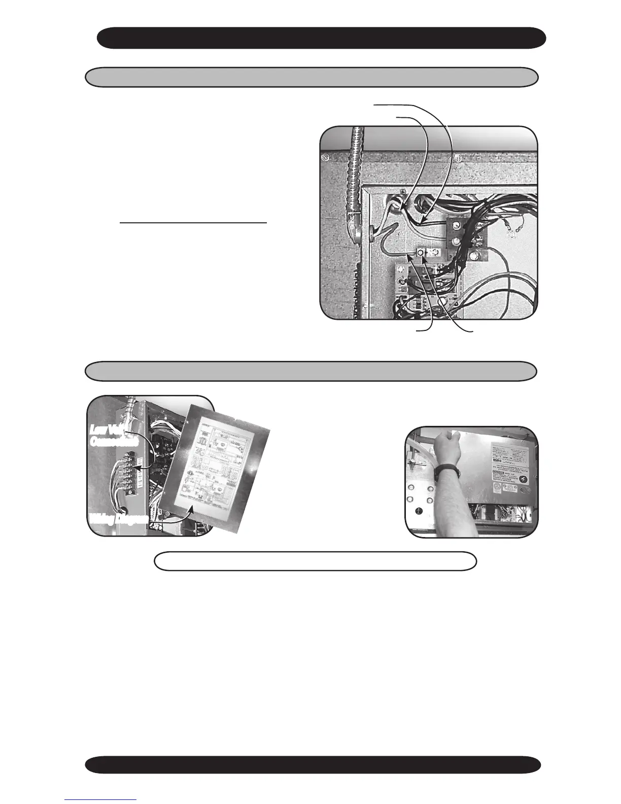
Low Volt Interconnect Wiring
Refer to the wiring diagram to connect the low Volt wiring to the
appropriate terminals. The wiring diagram located on
the inside of the control
box cover.
Once the connections
are made replace control
box cover with the wiring
diagram facing in and se-
cure with the four screws.
Low Volt
Connections
Wiring Diagram
The 24V control transformer is located in the air handler unit. This provides low volt
control power to both the air handler and condenser. Depending on the models selected,
the low volt interconnect control wiring may be different.
NOTE: All low volt interconnect wiring must be at least 18 AWG.
(L1)
(L2)
Ground Wire
Ground Lug
4. Then refer to the wiring diagram to
connect the power wire to (L1) and the
other wire to (L2) at the power connector
location (terminal block).
(See “Electrical Specifications” Sec-
tion in the back of this manual for more
information.)
Depending on the thermostat required or
selected, cooling only air handlers may
utilize three to ve low voltage intercon-
necting wires between the indoor unit,
thermostat and the outdoor unit. Some
thermostats do not require the use of the
“C” (brown) connection. In this case, en-
sure that any unused wires are insulated
to prevent them from making contact with
the junction box or other metal surfaces.
If the indoor unit has electric heat then a
“W” connection is required between the
thermostat and the indoor unit.
CASSETTE AIR HANDLER INSTALLATION INSTRUCTIONS