www.enviromaster.com
19
Cassette Air Handler
START -UP
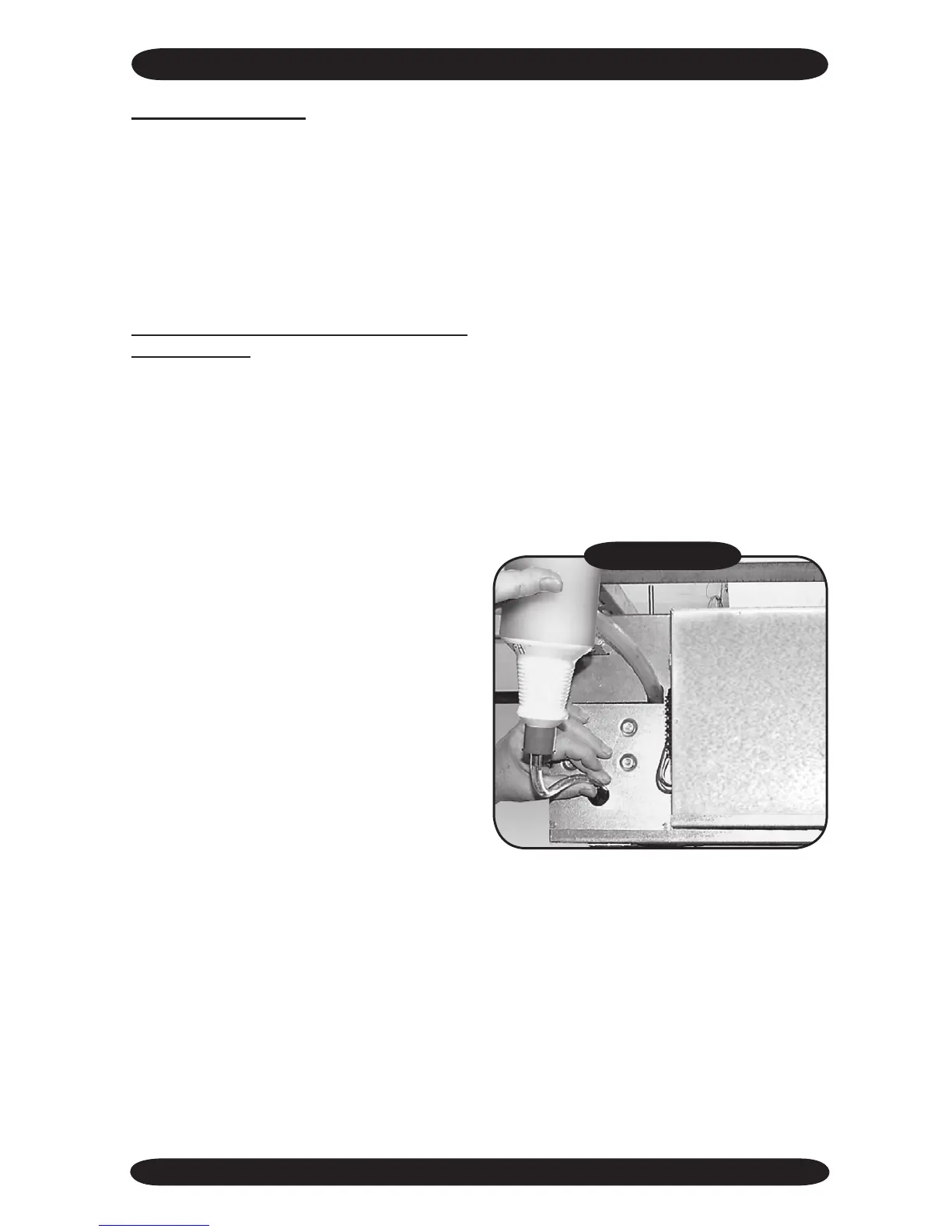
Figure #7
7. To check the operation of the condensate
pump remove an adjacent ceiling tile to
access the condensate pump access:
• Insert a squeeze water bottle nozzle
through the opening in the conden-
sate pump access panel and ll drain
pan. Refer to Figure #7.
• Adding water will activate the oat
switch and the pump. Water must
ow regularly with condensate pump
energized. If water does not, check
the pipe slope or see if there are any
pipe restrictions.
8. Ensure that all covers, panels and lters
are in place and discharge louvers are
correctly positioned.
Heat Pump Systems (See Conguration
Mode section of this document for details)
Heat Source – ON
Heat Pump – ON
Place the Optional Infrared Hand Held
Controller into heat mode with the set-
point temperature at least 2°F above room
temperature. Verify that the supply air is
warmer than room temperature.
CACB/CAHB – REMOTE THERMOSTAT
OPERATION:
2C. Verify that the DIP switches are con-
gured properly within the control box
of the air handler. Refer to Figure #6.
(See Sequence of Operation – Re-
mote Thermostat Mode section of this
document for details.)
#4 (Remote Thermostat Operation)
– ON
#3 (Remote Thermostat Fan Speed
Selection)
– OFF – Low Fan Speed
– ON – High Fan Speed
#2 (Remote Thermostat Louver Operation)
– OFF – No Louver Motion
– ON – Moving Louvers
#1 (Test Mode) is
– ON
3C. Using the wall thermostat turn on the
fan, verify fan operation and louver
function. Adjust either with the DIP
switches to preference.
4C. If the unit has Optional Electric Resis-
tance Heat, verify the operation of the
heating elements. (See Sequence of
Operation – Remote Thermostat Op-
eration section of this document for
details) and (Refer to the Thermostat
Owner’s Manual) for additional details
regarding the setpoint required to en-
ergize the heating elements. Due to
the large number of compatible ther-
mostat models that it is possible to
apply to this system, comprehensive
instructions can not be provided. For
additional assistance, please contact
our Technical Service Department at
1-800-228-9364.
5. Ensure that the Condensing Unit start
up procedure has been carried out as
detailed in the corresponding installa-
tion manual.
6. The compressor signal “Y” (disconnected
in step 1) can now be reconnected and
main power applied to the outdoor unit.
 Loading...


