www.enviromaster.com
33
Cassette Air Handler
SEQUENCE OF OPERATION
Once switched off, including following a
power outage, the compressor or heat
source will not re-start for a minimum of
three (3) minutes unless the unit is in Test
Mode then it’s forty ve (45) seconds.
STAGGERED START PROTECTION (Op-
:
Designed for systems with electric heat in
heat pump unit, the staggered start feature
will prevent the compressor and electric
heater from starting simultaneously. There
is a thirty (30) second delay between the
start of the compressor and start of the
electric heater in a heat pump system un-
less the unit is in Test Mode then it’s seven
and a half (7.5) seconds.
MINIMUM RUN TIME (OPTIONAL INFRA-
Once started, the Minimum Run Time
prevents either the compressor or heat
source from cycling off prematurely. The
minimum run time for both the compres-
sor and electric heat is two (2) minutes.
The Minimum Run Time feature is avail-
able only while the control is congured
for optional Infrared Hand Held Control
operation. Minimum Run Time is disabled
while in Remote Thermostat Mode. In Test
Mode, Minimum Run Time is thirty (30)
seconds.
DRAIN PAN SENSOR:
The drain pan sensors monitor the con-
densate level in the unit’s drain pan.
Should the water in the pan reach a critical
level, the monitor will automatically signal
the main control unit. The controls micro-
processor will switch off the condensing
unit for a minimum of three (3) minutes
AND until the fault condition has been
cleared, to prevent further condensate
production. A fault code of two (2) blinks
will ash on the Timer/Alarm LED and will
automatically reset once the fault condi-
tion is cleared.
ANNUNCIATION:
The unit is equipped with an annunciation
feature whereby the main control will beep
providing the user with audio feedback
conrming that the microprocessor has
successfully received commands from the
Optional Infrared Hand Held Controller.
The main control will also beep when the
Clear Filter Alarm button is held for three
(3) seconds indicating that the lter check
timer has been reset.
MEMORY BACKUP:
In the event of a power failure the con-
trol will retain all of its settings including
the mode of operation. When power is
restored, after a three (3) minute time
delay, the control will return to the mode
of operation that it was in prior to the
power failure.
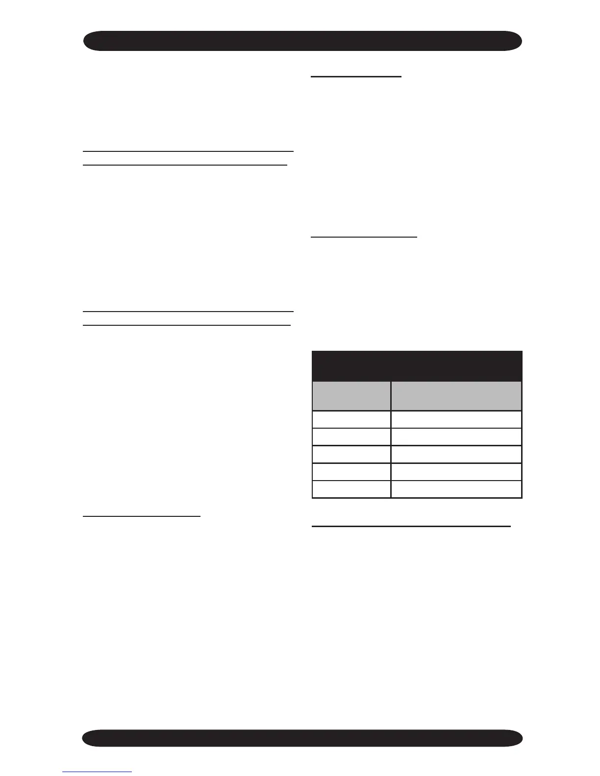
LED Trouble Blink Codes
(Timer/Alarm LED)
Number of
Blinks
Trouble
1 Room sensor fault
2 Condensate fault
3 Coil sensor fault
4 Clean lter
5 Test mode
ROOM AIR SENSOR FAULT 1 BLINK:
If the room air sensor is disconnected,
damaged or malfunctions the Timer/Alarm
LED will ash one (1) time to signify that
a fault has occurred. Operation of heating
and cooling will stop. The fan will continue
to operate.