www.enviromaster.com
9
Cassette Air Handler
1. Use the template (provided) to cut the
ceiling opening and determining the rod
positions.
2. Install hanger bolts using 3/8” (10mm)
all thread rod at the centers shown in
Figure #2.
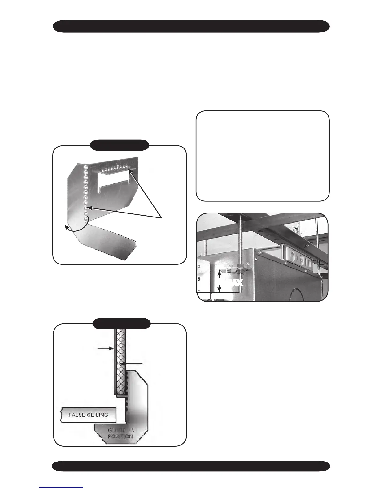
3. Prepare the installation guides by fold-
ing the metal bracket by hand along the
perforations, see Figure #3.
INNER CASE
INSULATION
CASSETTE
CASE
Figure #4
5. Secure unit in position with locknuts and
washers on either side of the Cassette
bracket.
6. Ensure threaded rod does not protrude
more than 2” (51mm) below the mount-
ing bracket.
4. Lift the Cassette onto the hanging rods.
Level at the correct distance from the
ceiling with the aid of the installation
guides as shown Figure #4.
CASSETTE CHASSIS POSITIONING AND INSTALLATION
Fold
bracket along
perforations
Figure #3
MAX
2”
(51mm)
NOTE: If the ceiling is not level or even, it is
important that the Cassette is installed level to
ensure correct pump operation and to maintain
fan clearances. Place a carpenter’s level on the
unit. A maximum slope of 1/8” (3mm) over the
length of the chassis toward the condensate
drain is allowed. Any slight discrepancy be-
tween the Cassette and ceiling will be taken up
by the fascia foam seal.