Do you have a question about the EMKO ESM 30 Series and is the answer not in the manual?
Provides details on physical and electrical installation of the device.
Covers user interface, parameter access, and descriptions.
Explains the meaning of warning and information symbols used in the manual.
Lists manufacturer name, address, product name, model, and category.
Declares conformity to directives and designed specifications.
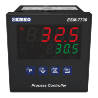
Outlines the general specifications and functional block diagram of the ESM-7730.
Details the codes for configuring supply voltage, input type, and outputs for ordering.
Details the warranty period and conditions for the EMKO Elektronik product.
Provides instructions for safe and effective maintenance of the device.
Highlights crucial safety warnings and precautions before and during installation.
Describes the front panel features, IP rating, and NEMA rating of the controller.
Provides the physical dimensions of the ESM-7730 controller and panel mounting size.
Specifies the required panel cutout dimensions for mounting the device.
Lists the operating temperature, humidity, altitude, and forbidden conditions.
Explains the step-by-step procedure for mounting the controller into a panel.
Details the use of the unit's own fixing clamps for secure panel mounting.
Provides instructions on how to safely remove the unit from its panel mount.
Details the terminal layout and provides instructions for electrical connections.
Presents the electrical wiring diagram for proper device connection and safety.
Shows a diagram of the labels and connection points on the device.
Explains the correct methods for connecting the device's power supply voltage.
Guides on connecting various sensor types (TC, RTD, Voltage/Current) to the process input.
Lists the galvanic isolation test values for various connections within the controller.
Illustrates the connection for the SSR driver output for process control.
Shows the wiring diagram for connecting Alarm Output-1 via a relay.
Details the connection for Process Output or Alarm Output-2 using a relay.
Explains the function of each LED, button, and display segment on the front panel.
Describes how to check the device's software revision number upon startup.
Guides on how to adjust process set values and alarm set values through the interface.
Provides a visual diagram of the program parameter structure for easy navigation.
Explains the procedure to enter and navigate the technician-specific menu.
Details the process for modifying and saving various parameters within the device.
Defines parameters for setting process values and alarm thresholds.
Covers advanced configuration settings for technicians.
Explains PID tuning methods (Auto Tune, Self Tune) and operation forms.
Defines what values are displayed on the top and bottom displays of the controller.
Covers selection of process input types (TC, RTD, Voltage/Current) and related parameters.
Details parameters for configuring PID control, including band, time, and output settings.
Configures settings for Process Output (SSR Driver) and Alarm Output-2 functions.
Details configuration options for Alarm Output-1, including logic and alarm types.
Details configuration options for Alarm Output-2, including logic and alarm types.
Covers general settings such as set value limits, protections, and button behavior.
Explains how to set up and use the technician password for parameter access.
Lists common failure messages and their meanings for troubleshooting.
Provides a summary of the device's technical specifications and characteristics.
Contains manufacturer contact details and repair service information.
| Type | Temperature Controller |
|---|---|
| Number of Outputs | 1 or 2 |
| Protection Class | IP20 |
| Input | Thermocouple |
| Output | Relay |
| Supply voltage | 100-240 V AC |
| Control Mode | ON/OFF, PID |
| Display | 4-digit LED |
| Operating Temperature | 0 to 50°C |