EasyManua.ls Logo

EMKO EAOM-6 User Manual

EMKO EAOM-6
40 pages
To Next Page IconTo Next Page
Page #1 background imageLoading...
Page #1 background image
EAOM-6 Automatic Generator Start Controller with Metering, 96x96 DIN Size
- Automatic engine start / stop
- Automatic shutdown on fault condition
- LED status and fault indication
- Alternator voltages and frequency measurement and monitoring
- Battery voltage measurement and monitoring
- Simple push-button controlled operation
- Over / under speed warning and shutdown
- Remote start / stop input
- Three user configurable inputs
- Provides charge alternator excitation current
- Two configurable relay outputs
- Speed sensing from alternator frequency or magnetic pickup
- Preheat feature
- Fully programmable
- RS-232 communication port
- Standard modem communication
-
Alternator voltages and frequency Battery voltage
Battery charging Engine running time
Engine RPM Engine Power
-
Engine fuel supply or engine stopping Preheat
Starter motor Alarm horn
Over / Under speed
-
Engine temperature Charging alternator
Oil pressure Emergency stop
Over / Under speed Low battery voltage
Voltage fail Weak battery alarm
Monitors
Controls
Fail Monitoring
Instruction Manual. ENG EAOM-6 02 V00 07/07
EAOM-6
Automatic Generator Start
Controller with Metering,
96x96 DIN Size
EAOM-6 SOFT
PC Communication Software for
Programming and Remote Monitoring

Table of Contents

Question and Answer IconNeed help?

Do you have a question about the EMKO EAOM-6 and is the answer not in the manual?

EMKO EAOM-6 Specifications

General IconGeneral
BrandEMKO
ModelEAOM-6
CategoryController
LanguageEnglish

Summary

EU DECLARATION OF CONFORMITY

PREFACE

1.1 General Specifications

Technical details of the EAOM-6 unit including voltage, frequency, and input/output capabilities.

1.2 Warranty

Outlines the warranty terms for the EMKO EAOM-6 equipment, valid for two years from delivery.

1.3 Maintenance

Instructions for cleaning and repair, emphasizing use of trained personnel and specific cleaning agents.

INSTALLATION

2.1 General Description

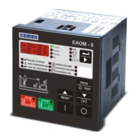
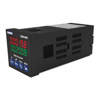
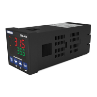
Overview of the EAOM-6 unit, its front panel features, and IP rating.

2.2 Dimensions

Provides physical dimensions of the EAOM-6 unit and its panel mounting requirements.

2.3 Panel Cut-Out

Specifies the required dimensions for the panel opening for mounting the EAOM-6 unit.

2.4 Environmental Ratings

Details operating conditions, temperature, humidity, altitude, and forbidden environments for the EAOM-6 unit.

2.5 Panel Mounting

Step-by-step guide for mounting the EAOM-6 unit into a control panel, including safety precautions.

2.6 Installation Fixing Screws

Explains the method of panel mounting using fixing screws and highlights safety during installation.

2.7 Removing from the Panel

Step-by-step instructions for safely removing the EAOM-6 unit from its panel mounting.

ELECTRICAL WIRINGS

3.1 Terminal Layout and Connection Instructions

Details the terminal layout of the EAOM-6 and provides instructions for electrical connections.

3.2.1 1-Phase Wiring Diagram

Illustrates the electrical wiring connections for a 1-phase system using the EAOM-6 controller.

3.2.2 3-Phase Wiring Diagram

Illustrates the electrical wiring connections for a 3-phase system using the EAOM-6 controller.

RS-232 SERIAL INTERFACE, PROGRAMMING THE DEVICE OVER PC OR MODEM

4.1 RS-232 Cable Connections

Details cable connections for PC and modem interface via RS-232.

4.3 PC Interface Software

Explains the EAOM-6 PC software, its windows, menus, and parameter access.

4.3.13-4.3.16 File Operations

Covers loading, saving, uploading, and downloading configuration files and parameters using the PC software.

PARAMETERS

5.1 Program Functions

Details various programmable functions of the EAOM-6, including voltage, frequency, and speed settings.

5.2 Changing and Saving Operator Parameter Value

Step-by-step guide on how to change and save operator parameter values on the EAOM-6 unit.

5.3 Changing and Saving Technician Parameter Value

Step-by-step guide on how to change and save technician parameter values on the EAOM-6 unit.

LAMP TEST

OPERATION

7.1 Front Panel Description

Detailed explanation of the EAOM-6's front panel buttons, display, and indicator LEDs.

7.2 Display Mode Indicators

Explains the different display modes and indicators on the EAOM-6, including error messages.

7.3 Starting the Engine

Outlines the procedure for starting the generator engine using the EAOM-6 controller.

7.4 Stopping the Engine

Explains how to stop the generator engine using the EAOM-6 controller's stop button or remote input.

COMMISSIONING

FAULT FINDING

9.1 Fault Indications

Details fault indicators, error messages, and troubleshooting steps for common issues with the EAOM-6 unit.

SPECIFICATIONS

Related product manuals