All rear connectors are two-part removable and can be unplugged to facilitate fast and convenient connection. If remote start
operation is required, the installer should ensure sufficient visual and audible warning takes place before commanding the start
sequence.
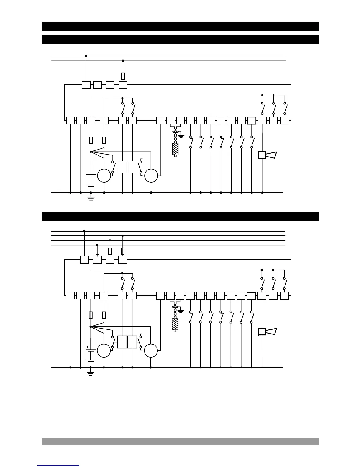
FUSE-1 should meet the current required by horn and configurable output ( Max. 15 A. T)
FUSE-2 should meet the current required by solenoids ( Max.16 A. T)
FUSE-3, FUSE-4, FUSE-5 should be 1 A. T
GENERATOR
N
L
BATTERY
+BATTERY
+BATTERY
GENERATOR VOLTAGE
FUSE-5
5A
5A
5A
HORN
CONFIG.OUT1
CONFIG.OUT2
CONFIGURABLE INPUT3
CONFIGURABLE INPUT2
CONFIGURABLE INPUT1
LOW OIL PRESSURE
HIGH TEMPERATURE
REMOTE START/STOP
EMERGENCY STOP
14
17
16 15
9 8
7
2 1
3
18 26
27
19 20
21 22
23
24 25
4
6
5
STARTER
START
RELAY
FUEL/
STOP
RELAY
FUSE-2
FUSE-1
12A
12A
D+(W.L)
B+
40A
CHARGE GENERATOR
Magnetic
Pickup
(up to 10kHz)
CHARGE
GEN.
40A
+
BATTERY NEGATIVE MUST BE GROUNDED
SGN
GND
c
1
c
1
c
2
GENERATOR
N
L1
L2
L3
17
14
16 15
9 8
7
2 1
3
18 26
27
19 20
21 22
23
24 25
4
6
N
L1
L2
L3
LOAD
BATTERY NEGATIVE MUST BE GROUNDED
-BATTERY
+BATTERY
+BATTERY
FUSE-1
FUSE-2
BATTERY
5A
5A
5A
HORN
CONFIG.OUT1
CONFIG.OUT2
CONFIGURABLE INPUT3
CONFIGURABLE INPUT2
CONFIGURABLE INPUT1
LOW OIL PRESSURE
HIGH TEMPERATURE
REMOTE START/STOP
EMERGENCY STOP
STARTER
START
RELAY
FUEL/
STOP
RELAY
D+(W.L)
B+
40A
CHARGE GENERATOR
Magnetic
Pickup
(up to 10kHz)
CHARGE
GEN.
40A
GENERATOR VOLTAGE
FUSE-5
FUSE-4
FUSE-3
SGN
GND
12A
12A
5
c
2
c
1
c
1
1- Connect the unit as shown in the appropriate diagram above. Be sure to connect the battery supply the right way round and
battery negative should be grounded. The connectors can be unplugged from the rear of the unit to facilitate connection.
2- Screened cable must be used for connecting the Magnetic Pickup, ensuring that the screen is grounded at one end ONLY.
c
3.2 Electrical Wiring Diagram
3.2.1 1-Phase Wiring Diagram
3.2.2 3-Phase Wiring Diagram
13
-BATTERY