Warning: Beware of the high voltages connected to this unit.
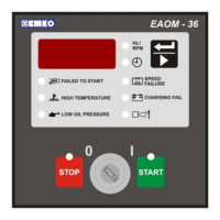
Indicators on the central section of the panel will flash if a fault is detected. If a fault is indicated,
proceed as follows:
1. Find and fix the fault.
2. Press the Reset button to enable a restart.
3. Press the Engine Start button
In addition to the indicators on the center panel, the Alarm LED will flash in the event of a fault. To
discover the fault being reported by the Alarm LED, press repeatedly until the Alarm option has
been selected. The display will indicate the fault condition, as follows:
This LED flashes if the engine has not started after the programmed Number of Starting Attempts
(P23). The unit must be reset, by pressing the Failure Reset (9) button, before a fresh attempt can
be made.
This LED flashes if the thermostatic switch on the engine indicates high temperature. If this fault
occurs, the EAOM-6 will stop the engine without any Engine Cooling Time (P29).
This LED flashes if the Oil Pressure Switch on the engine indicates low oil pressure while the
engine is running. To obtain this indication, the engine must have been running for at least the
period specified by the Oil Pressure By-Pass Time (P25). If this fault occurs, the EAOM-6 will stop
the engine without any Engine Cooling Time (P29).
This LED flashes and the horn sounds if the output from the battery charge generator fails after
the engine has started. The fault will not be indicated if it occurs within the period defined by the
Control On Delay parameter (P26) after the engine has started. This failure will not shut down the
engine.
This LED flashes if the alternator speed goes outside the values defined by the Speed Lower
Limit (P02) and Speed Higher Limit (P03) parameters. For a fault to be indicated, the speed must
be outside these limits for longer than the period defined by the Speed Fault Control Delay
parameter (P28). Alternator speed is measured either by measuring alternator output frequency
or by monitoring an external magnetic pick-up as selected by program Speed Sensing Input
Selection parameter (P15). This failure immediately stops the generating set without any Engine
Cooling Time (P29)
9. FAULT FINDING
9.1 Fault indications
9.1.1 Failed to Start LED
9.1.2 High Temperature LED
9.1.3 Low Oil Pressure LED
9.1.4 Charge Generator Failure LED
9.1.5 Over / Under Speed LED
9.1.6 Generator Voltage Failure LED
Spare inputs 1, 2 and 3. These show the states of the Spare inputs on pins 23, 24, 25. The
indications may be either latched or momentary.
9.1.7 Spare-1, 2, 3
36
This failure is indicated if the generator runs for Control On Delay (P26) time. This LED flashes if
the alternator output voltage is outside of the limits programmed into Alternator Voltage Lower
Limit (P00), and Alternator Voltage Upper Limit (P01), for a time period longer than the Alternator
Voltage Fault Control Delay (P27). This failure immediately releases the generator contactor, and
stops the generating set without any Engine Cooling Time (P29) period.