17
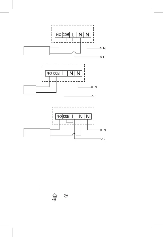
Floor Heating Connection Diagram
Connected
device
Boiler Connection Diagram
Boiler
• The pre-installed wire coupler will not be connected.
Expansion Valve/Electric Drive Connection Diagram
Connected
device
PUTTING THE DEVICE INTO OPERATION
Pairing the Control Unit with the Switching Unit
Both thermostat units must be paired before rst use.
Pairing enables transmission of information between the control unit and the
switching unit.
Setting is done via automated pairing (self-learning).
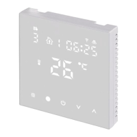
1. Fit the thermostat gently onto the stand.
Connect the USB power supply with micro USB cable to 230 V mains and
plug the cable into the stand.
2. Correctly connect the switching unit to voltage supply, turn the main switch
to the position and long press (for at least 10 seconds) the M/A button; a
green LED will begin ashing on the MANUAL button.
3. Long-press the and buttons on the thermostat (transmitter) for about
5 seconds; the icon will start ashing.
Both units will be paired within 1 minute and the green diode on the switching
unit will stop ashing.