30794-5-0314Page 16
Installing Vent Components
Begin the vent system installation by installing the rst Simpson
Duravent component on the top of the appliance with a 45° elbow
and rotate the vent elbow to the desired position then add horizontal
and vertical pipe lengths and then a horizontal or vertical termination
kit. Elbows can be added where necessary. See Pages 11 through
15 for venting requirements.
Simpson Duravent vent system components lock into place by
sliding the concentric pipe section with four equally spaced interior
beads onto the appliance collar or previously installed component
end with four equally spaced indented sections. When the internal
beads of each starting 6 5/8 inch outer pipe line up, rotate pipe
section clockwise 90° (approximately 3 inches). The vent pipe is
now locked together.
Continue adding components per the pre-planned vent system
conguration. Be certain that each succeeding vent component
is securely tted and locked into the preceding component in the
vent system.
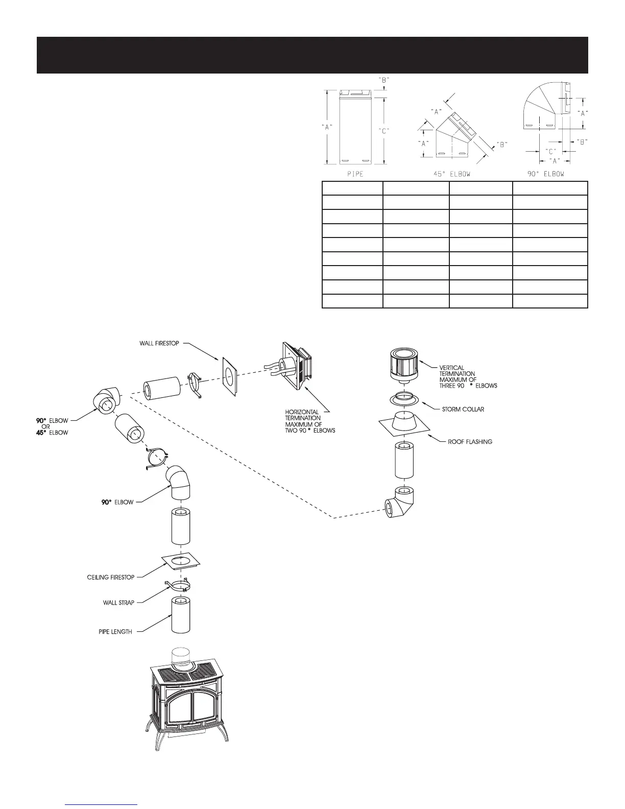
Figure 13
Figure 12
VENT SYSTEM IDENTIFICATION
PART NAME "A" "B" "C"
6" PIPE 6" (152 mm) 1 1/2" (38 mm) 4 1/2" (114 mm)
9" PIPE 9" (229 mm) 1 1/2" (38 mm) 7 1/2" (191 mm)
12" PIPE 12" (305 mm) 1 1/2" (38 mm) 10 1/2" (267 mm)
24" PIPE 24" (610 mm) 1 1/2" (38 mm) 22 1/2" (572 mm)
36" PIPE 36" (914 mm) 1 1/2" (38 mm) 34 1/2" (876 mm)
48" PIPE 48" (1.220 m) 1 1/2" (38 mm) 46 1/2" (1.18 m)
45° ELBOW 5 1/2" (140 mm) 1 1/2" (38 mm) ---
90° ELBOW 6 1/2" (165 mm) 1 1/2" (38 mm) 5" (127 mm)