4
Wiring diagram and electrical integration
All unused wires of the wire harness must be cut, insulated and tied separately.
Power supply
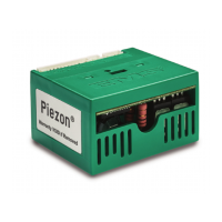
- For 24 V AC installation: Connect both pin 10 AC1 and pin 11 AC2 of the EJ-110 module to the 24V AC power source of the unit. For
this type of use, it is important to do an extra operation on the wire harness to connect pin 12 DCI with pin 2 DCO.
- For 32 V DC installation: If your unit has a DC source providing a voltage of 32 V DC, connect both pin 12 DCI and pin 13 0VP of the
EJ-110 module to the power source of the unit.
Never connect both AC and DC power supplies as this would damage the module.
Ultrasound power ON/OFF
Ultrasound generation can be enabled or disabled in two different ways:
Power ON/OFF method Modules types Installation and effects
By activating or deactivating power
supply (standard mode)
F, H Ultrasounds will start immediately when the power supply is turned
on. Make sure the Scaler Switch pin 9 ONL is not connected (open)!
Impact on LED (only for LED version): The 20 sec LED timer will not
work in that mode.
By using the digital Scaler Switch E, G This mode allows to use the 20 seconds delay time on the LED
handpiece (only for LED version). In that mode, the power supply to
the module needs to remain activated.
Put pin 9 ONL to 0 VDC to activate the ultrasounds and to 5 VDC or
OPEN to switch ultrasounds OFF.
Scaler power control
The ultrasonic power of the EJ-110 module can be set using two different modes, either by the use of a potentiometer or via an analogue 0-5
or 0-10 Vdc set-point voltage.
Scaler power control Modules types Installation and effects
Potentiometer E, F The power regulation using this mode requires a 2.2 kOhm manually
operated potentiometer that is delivered with the product.
To connect the potentiometer, please refer to the wiring diagram on
page 6.
0 – 5 / 0 – 10 Vdc G, H The output power can be set with an analog voltage of 0-5Vdc or
0-10Vdc.
To connect the EJ-110 module with the dental unit control
electronics, please refer to the wiring diagram on page 5.
LED control by the dental unit
It is possible to supply the handpiece LED directly via the dental unit electronics instead of the module. This will require a controlled 5 V DC /
150 mA source. To do so, cut the 2-pin connector from the handpiece cord (white and violet wires) and connect the violet wire to 5 V DC and
the white wire to ground.
FB-609_KR_ed_2015_11_Installation manual PIEZON BUILT IN BIK.indd 4 01.04.2016 14:34:42
 Loading...

