Document no. 10060104
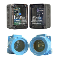
IRB-4X Transmitter connections (figure 1)
1. Connect power (12 – 24V AC/DC) to Power
input terminals (no polarity) LED2 Power LED will
glow green when powered.
IRB-4X Receiver connections (figure 2)
Terminal output connections from left to right are:
Normally closed, Common, Normally open, Power, Power
1. Connect power (12 – 24V AC/DC to Power input terminals (no polarity)
2. Connect the Common to the operator control terminal per manufacturer
3. Connect either the Normally open or Normally Closed as needed to the
Control input terminal specified by the operator manufacturer.
4. The Power LED will glow green when powered.
5. Adjust sensitivity potentiometer as needed by turning counter clockwise
to increase gain. (range is 3 to 115 feet). (see arrow)
6. The detect Led will glow red when an obstruction occurs.
7. On some variable frequency drives and noisy installations, it may be necessary
to connect the bottom right mounting hole labeled
“Earth Ground” to a wire connected to earth ground.
* Do not connect unless necessary
Use minimum gain setting needed to achieve reliable detection.