• 3 phase generator current inputs
• 12 or 24 V battery supply input
• Oil pressure and temperature analog inputs
• Charge alternator input
• Cranking relay output
• Preheat relay output
• Fuel solenoid relay output
• Mains contactor relay output
• Generator contactor relay output
• Alarm relay output
• 2 programmable auxiliary relay output
• 2 programmable auxiliary input
ALARMS
• Engine start/stop failure
• Under/over speed failure
• Under/over voltage failure
• Over current failure
• High temperature failure
• Charge fail warning
• Low oil pressure failure
• Periodic service time warning
• Auxiliary failure
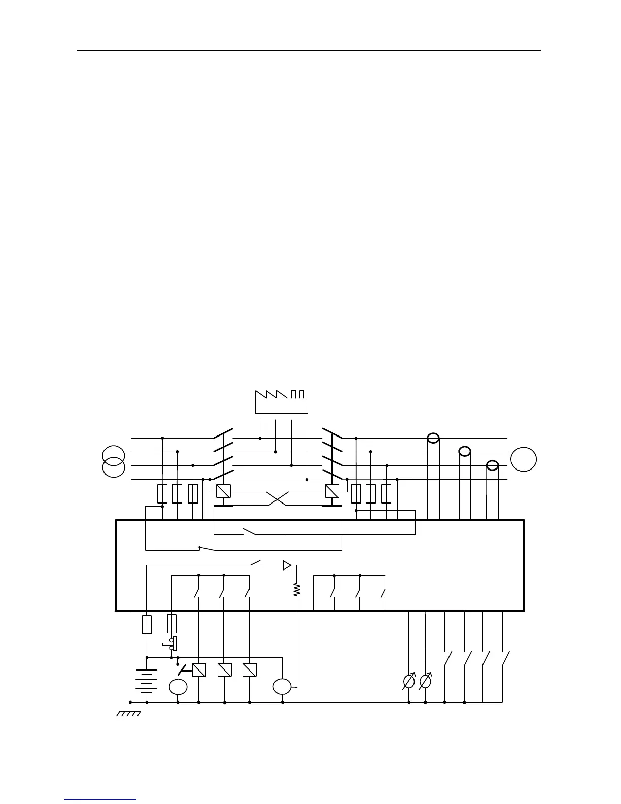
AMF 4.0 CONNECTION DIAGRAM
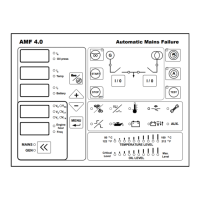
AMF 4.0
Generator Contactor
Relay
Mains Contactor Relay
G
R
S
T
N
U
V
W
N
LOAD
R S
T N
GENERATORMAINS
12
23
19
18
17
22
11 14
353433
32
31
30
2928
27
26
25
24
Configurable Input 1
(Default Oil Pressure Switch)
Configurable Input 3
Battery
1
2
Oil Pressure sender
Temperature Sender
Crank
Charge
Fuel Selenoid
Preheating Ralay
3
5 212010
98
7
15
6
4
Configurable output 1
(Default Horn)
D+WL
Power Supply
Crank Relay
13
Emergency
Stop
Com 2
16
Configurable Input 4
Generator Current
Inputs
Configurable output 2
Configurable output 3
Configurable Input 2
(Default Temperature Switch)
NEGATIVE TERMINAL OF BATTERY
SHOULD BE GROUNDED